Full-automatic lubricating oil evaporation loss tester

A technology of evaporation loss and measuring instrument, which is used in instruments, non-electric variable control, analysis of materials, etc., can solve the problems of high labor consumption, poisoning and pathogenic testers, and large differences in test results, and achieves good pressure regulation stability. , High degree of automation, easy to track the effect of query

Active Publication Date: 2014-06-18
大连瀚泰科技有限公司
View PDF2 Cites 2 Cited by
  • Summary
  • Abstract
  • Description
  • Claims
  • Application Information

AI Technical Summary

Problems solved by technology

[0002] In the lubricating oil and grease industry, the evaporation loss value of lubricating oil is an important index in lubricating oil parameters, and it is one of the important basis for evaluating the lubricating effect and life of lubricating oil. At present, the domestic determination of the evaporation loss of lubricating oil and grease base oil The manual test method is still used to test the value, and Wood alloy is used as the auxiliary heating medium. This measurement method has the following disadvantages: 1. During the manual test, the pressure parameters need to be adjusted by manual observation. Manual negligence can easily lead to abnormal pressure, and the adjusted value is stable. Poor performance, which affects the accuracy of the test results; 2. Using Wood alloy as the heating medium, when it is heated to the melting temperature, it will produce toxic vapors that will be emitted into the space, causing harm and impact to the testers and the environment, and in severe cases will cause testers Poisoning
3. The test cycle is long (the whole process is more than 1 hour), and the whole test process needs to be observed and adjusted by the testers at all times, which consumes a lot of manpower: 4. The difference in the testing energy and testing experience of the testers will lead to great differences in test results , unable to meet the accuracy, repeatability and reproducibility required by relevant standards

Method used


Image

  • Full-automatic lubricating oil evaporation loss tester
  • Full-automatic lubricating oil evaporation loss tester
  • Full-automatic lubricating oil evaporation loss tester

Examples


Embodiment 1

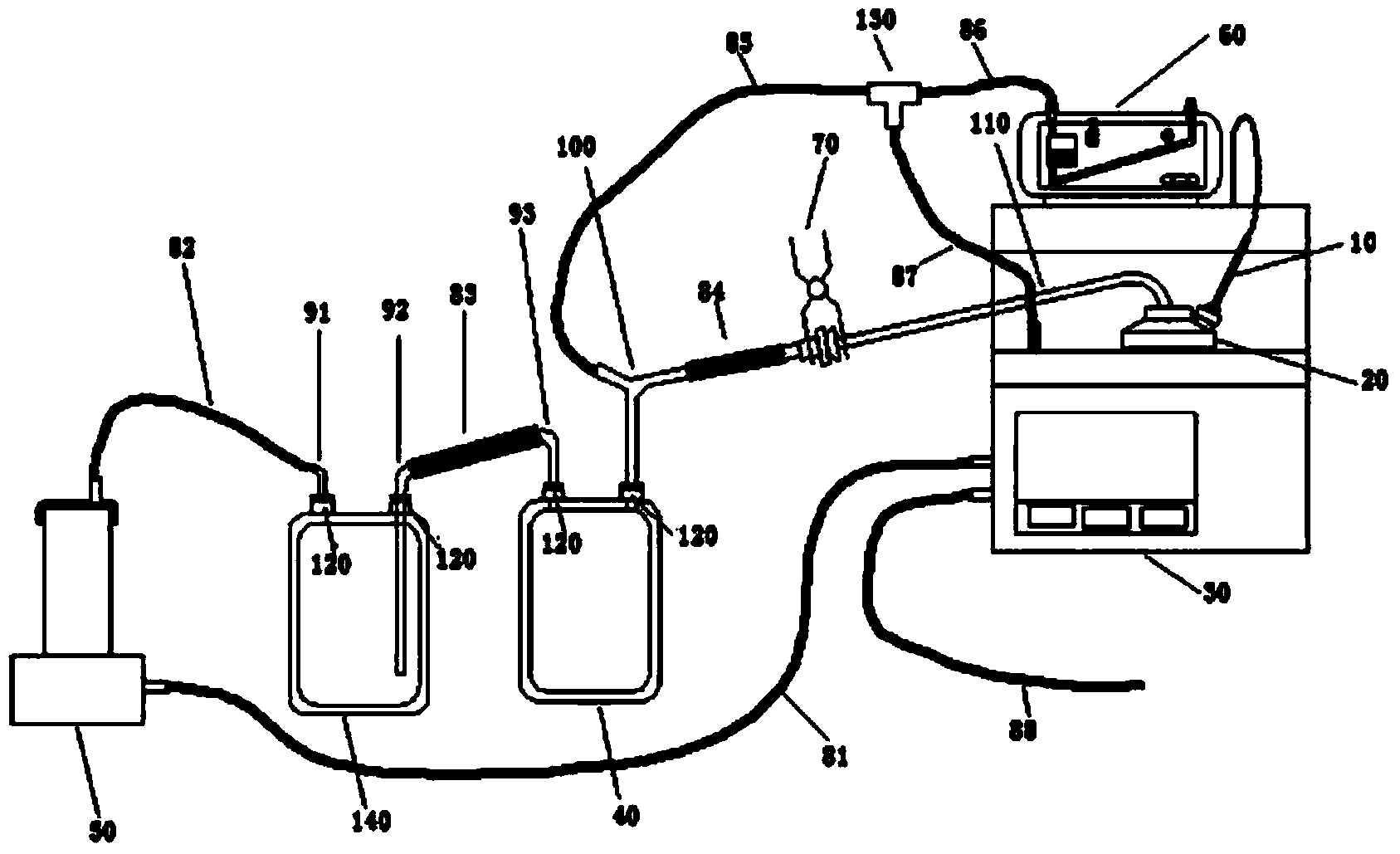
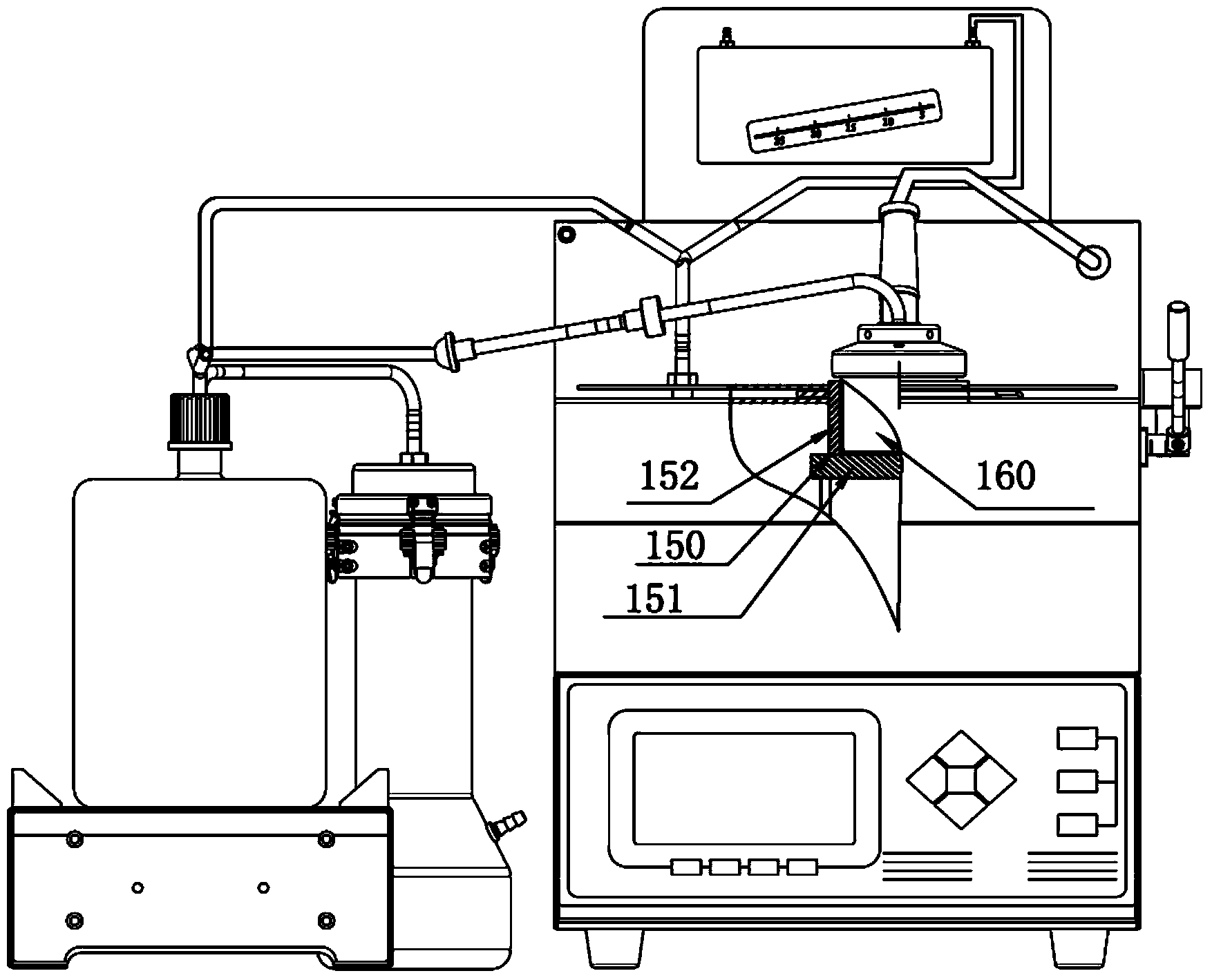
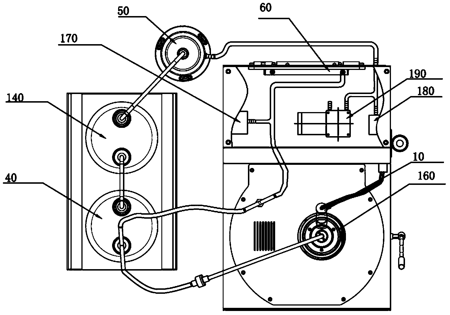
[0030] Such as Figure 1~4 The automatic lubricating oil evaporation loss tester shown includes a tester body 30, an electric heating element 150, an evaporation crucible 160, a temperature sensor 10, a pressure sensor 170, an inclined differential pressure gauge 60, a pressure controller 180, and a vacuum pump 190. First-level buffer bottle 40, second-level buffer bottle 140, filter 50, silicone tube Ⅱ 82, silicone tube Ⅲ 83, silicone tube Ⅳ 84, glass branch pipe Ⅰ 91, glass branch pipe Ⅱ 92, glass branch pipe Ⅲ 93, Y-shaped glass tube 100, evaporation crucible Extraction pipe 110, glass tee pipe 130;

[0031] The measuring instrument body 30 includes a measuring instrument housing, a supporting plate, a central processing unit and a control circuit.

[0032] The electric heating element 150 is installed inside the measuring instrument body 30, and includes a bottom heater 151 and a shell heater 152. The bottom heater 151 and the shell heater 152 form an annular groove, and the e...


PUM


Abstract

The invention provides a full-automatic lubricating oil evaporation loss tester. The full-automatic lubricating oil evaporation loss tester comprises a tester body, an electrical heating element, an evaporator crucible, a temperature sensor, a pressure sensor, an inclined differential pressure gauge, a pressure controller, a vacuum pump, a primary surge flask, a secondary surge flask, a filter, a silicone tube II, a silicone tube III, a silicone tube IV, a glass branch pipe I, a glass branch pipe II, a glass branch pipe III, a Y-shaped glass pipe, an evaporator crucible extraction pipe and a glass T-branch pipe; and the tester body comprises a tester shell, a support panel veneer, a central processor and a control circuit. The tester is used for determining base oil evaporation loss of lubricating oil and lubricating grease in the industries of scientific research, production and use of lubricating oil, and achieves full-automatic determination of lubricating oil evaporation loss by adjusting the temperature, the pressure, the air velocity and other parameters under specified conditions.

Description

Technical field [0001] The invention relates to a detection device for detecting the evaporation loss value of lubricating oil and grease base oil. Background technique [0002] In the lubricating oil and grease industry, the value of lubricating oil evaporation loss is an important indicator of lubricating oil parameters and one of the important basis for evaluating the lubricating effect and life of lubricating oil. At present, the evaporation loss of lubricating oil and grease base oil is measured in China The value still uses the manual test method, and Wood's alloy is used as the auxiliary heating medium. This measurement method has the following drawbacks: 1. During manual testing, the pressure parameters need to be adjusted by manual observation. Manual negligence can easily lead to pressure abnormalities and stable adjustment values. Poor performance, affecting the accuracy of the test results; 2. Using Wood's alloy as a heating medium, after heating to the melting temper...

Claims


Application Information

Patent Timeline
Patent Type & Authority Applications(China)
IPC IPC(8): G01N35/00G01N33/28G05D27/02
Inventor 刘云生
Owner 大连瀚泰科技有限公司
Why Eureka
Try Eureka