
Nuclear power plant control rod position measurement method

A measurement method and control rod technology, which are applied in nuclear power generation, nuclear engineering, nuclear reactor monitoring, etc., can solve the problems of complex control and monitoring circuits, large number of cable cores, and large interference of measurement coils, so as to improve reliability and availability, Achieve technological maturity and reduce the number of cables

Active Publication Date: 2014-06-18
NUCLEAR POWER INSTITUTE OF CHINA
View PDF6 Cites 5 Cited by
  • Summary
  • Abstract
  • Description
  • Claims
  • Application Information

AI Technical Summary

Problems solved by technology

[0005] 1) The structure is complex, including three coil components with different functions, namely 1 secondary coil, 2 auxiliary coils and 31 measuring coils, and has high requirements for electrical insulation and signal isolation between coils
[0006] 2) The control and monitoring circuit is complicated, and the secondary coil needs to be adjusted in a closed loop; the interference between the measuring coils is large, which is not convenient for the processing of the rod position signal, and it is also not convenient for on-site debugging and testing
[0007] 3) There are more signal lines, more cores are required for cables, and more mandrels are required for cable penetrations
[0008] 4) The failure rate is high. If any of the three coils fails, or any rod position measurement channel (including the secondary coil excitation circuit, the measurement coil signal processing circuit, etc.) fails, one control rod will be lost. Measuring rod position, which affects the operation of the reactor and thus the economics of the nuclear power plant

Method used


Image

  • Nuclear power plant control rod position measurement method

Examples


Embodiment Construction

[0017] The present invention is described in detail below in conjunction with accompanying drawing and embodiment:

[0018] A method for measuring the position of a control rod in a nuclear power plant, comprising the steps of:

[0019] (1) Use the measuring coil of the rod position detector to measure, and divide the measuring coil into two independent coil groups—group A and group B. Group A is composed of odd groups of coils, and group B is composed of even groups of coils. Multiple coils of a group of measuring coils are connected in parallel.

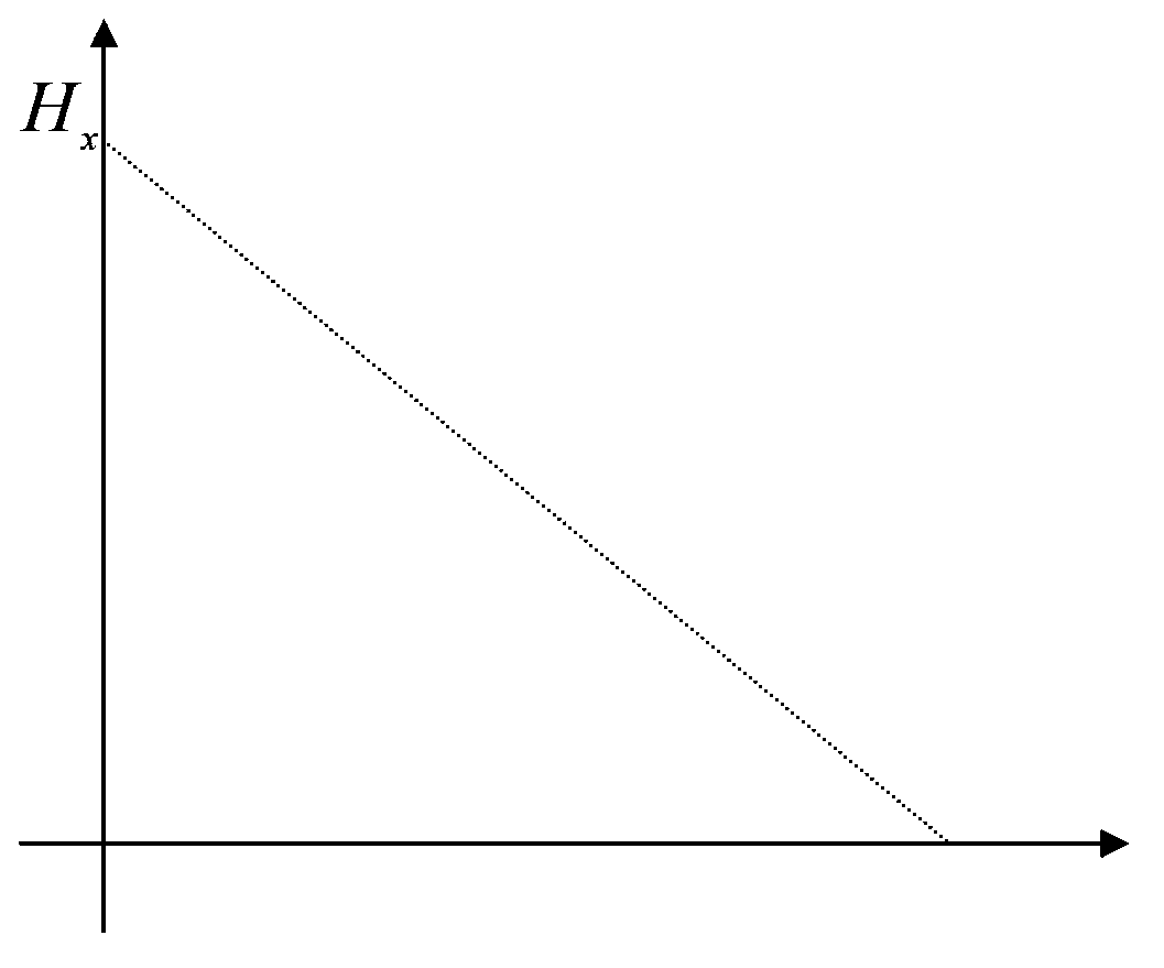
[0020] (2) Apply AC constant voltage excitation to the coils of group A and group B respectively, and use the external excitation power to generate alternating magnetic field and current. When the control rod screw is at different positions in the detector, the coil impedance of the rod position detector changes , so that the excitation current I of the two sets of coils xA , I xB change occurs by measuring the I xA , I xB Two...


PUM


Abstract

The present invention relates to a rod position measurement method. The principle is that an external excitation power supply is adopted to produce an alternating magnetic field and a current, and the inductive reactance of a rod position detector is changed when the screw rod of a control rod is positioned at different positions in the detector, such that the exciting current of a measurement coil is changed so as to acquire the control rod position; the measurement coil and the measurement channel thereof are divided into two completely separate groups so as to be treated, redundancy is formed, and the two groups of the signals are combined when the two groups of the measured rod positions are normal so as to produce the full precision measurement rod position signal; and the half-precision measurement rod position of the control rod is produced if only the one group of the rod position signal is normal. According to the present invention, the rod position measurement method has high reliability and high availability, can be used for improving the existing rod position measurement method on the basis of maintaining of the original rod position detector structure, and is further used for the new rod position detector.

Description

technical field [0001] The invention belongs to a measurement method for a pressurized water reactor nuclear power plant, in particular to a method for measuring the position of control rods in a nuclear power plant—a method for measuring excitation current in parallel with multiple coils. Background technique [0002] The rod bundle control assembly (RCCA) is located in the high temperature and high pressure environment of the primary circuit, and the measurement of its position is generally carried out by the principle of electromagnetic induction. [0003] At present, the rod position detectors of domestic pressurized water reactor nuclear power plants mainly include primary coils (also called primary coils), measuring coils, auxiliary coils, coil skeletons, sealing shells and outer sleeves and other components. The primary coil is a long solenoid that is wound along its entire stroke. Both the measuring coil and the auxiliary coil are secondary coils, coaxial with the p...

Claims


Application Information

Patent Timeline
IPC IPC(8): G21C17/10
CPCY02E30/30
Inventor 黄可东蔡晨李国勇余海涛田宇刘明星郑杲
Owner NUCLEAR POWER INSTITUTE OF CHINA
Features
  • Generate Ideas
  • Intellectual Property
  • Life Sciences
  • Materials
  • Tech Scout
  • Unparalleled Data Quality
  • Higher Quality Content
  • 60% Fewer Hallucinations
Learn More