Linear motor and platform device

A linear motor and current technology, applied in the field of photolithography, can solve the problems of inability to accurately position equipment, insufficient controlled force, and difficult control accuracy of the yoke, and achieve the effects of simple structure, increased vertical magnetic flux, and convenient operation

Inactive Publication Date: 2014-06-18
SHANGHAI MICRO ELECTRONICS EQUIP (GRP) CO LTD
View PDF11 Cites 15 Cited by
  • Summary
  • Abstract
  • Description
  • Claims
  • Application Information

AI Technical Summary

Problems solved by technology

However, considering the ripple force (ripple) caused by tilt interference, etc., it is impossible to accurately locate the device
And considering the influence of the cuboid magnets aligned side by side on the magnetic

Method used


Image

  • Linear motor and platform device
  • Linear motor and platform device
  • Linear motor and platform device

Examples


Embodiment 1

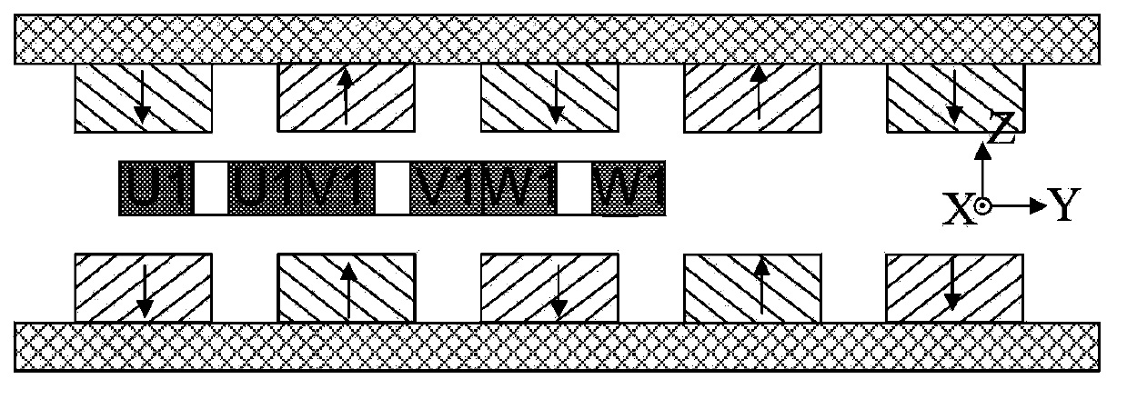
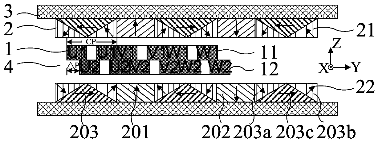
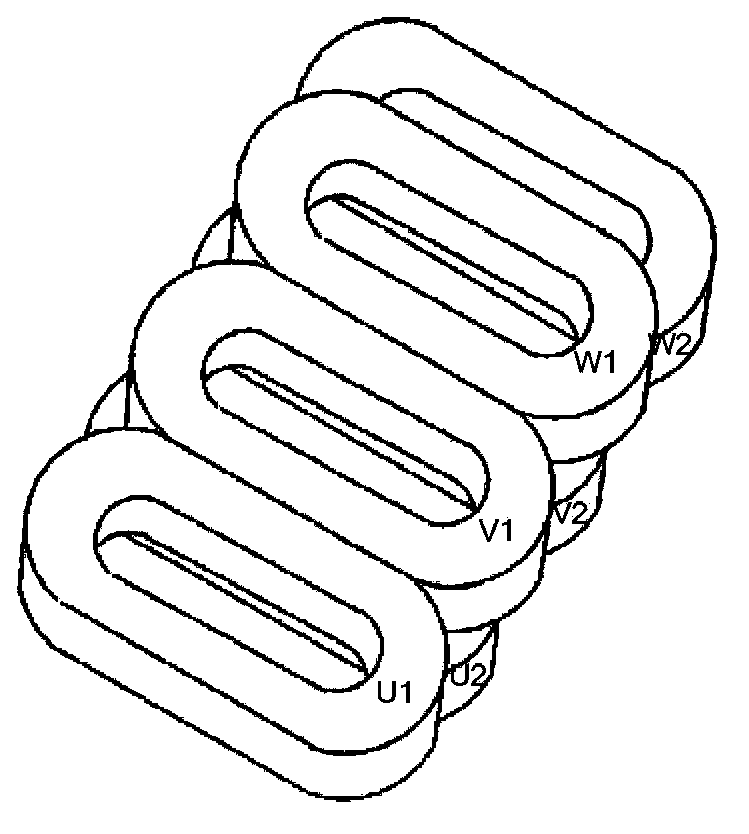
[0036] see figure 2 , a linear motor provided in this embodiment includes a magnet unit 2 and a coil unit 1, a magnet holder 3 and a control system (not shown), and the magnet holder 3 is lateral (XZ plane in this embodiment) U-shaped, used to support the magnet unit 2; the magnet unit 2 includes a first magnet array 21 and a second magnet array 22 respectively located on the two parallel inner walls of the magnet holder 3; the coil unit 1 is set The magnetic gap 4 between the two groups of magnet arrays is set at the magnetic gap 4 between the first magnet array 21 and the second magnet array 22. The control system is used to provide current to the coil unit 1, so The first magnet array 21 and the second magnet array 22 are distributed periodically and alternately along the Y direction according to the Halbach array pattern, please refer to image 3 The coil unit 1 includes a first coil array 11 and a second coil array 12 stacked in the Z direction, and the first coil array...

Embodiment 2

[0045] see Figure 8 , the difference between this embodiment and implementation 1 is:

[0046] The cross-sections of the first prism magnet 203a, the second prism magnet 203b and the third prism magnet 203c along the YZ plane are right triangle, isosceles trapezoid and right triangle respectively. The first magnet array 21 and the second magnet array 22 composed of the third type magnet 203 , the first type magnet 201 and the second type magnet 202 with the above structure are adopted. In this embodiment, the required vertical suspension force can also be generated; the ripple force caused by tilt interference can be eliminated to provide the required control torque, eliminate the torque, and achieve precise positioning; the vertical magnetic flux can be increased to produce a greater response Horizontal thrust, and has the advantage of less magnetic leakage.

Embodiment 3

[0048] see Figure 9 , the difference between this embodiment and implementation 1 is:

[0049] The cross-sections of the first prism magnet 203a, the second prism magnet 203b and the third prism magnet 203c along the YZ plane are right trapezoid, isosceles triangle and right trapezoid respectively. The cross sections of the first prism magnet 203 a and the third prism magnet 203 b along the YZ plane are right-angled trapezoids with a common side. The first magnet array 21 and the second magnet array 22 composed of the third type magnet 203 , the first type magnet 201 and the second type magnet 202 with the above structure also have the advantage of smaller magnetic leakage. In this embodiment, the required vertical suspension force can also be generated; the ripple force caused by tilt interference can be eliminated to provide the required control torque, eliminate the torque, and achieve precise positioning; the vertical magnetic flux can be increased to produce a greater r...


PUM


Abstract

Disclosed is a linear motor which comprises a magnet unit, a coil unit, a magnet fixing seat and a control system. The magnet fixing seat is laterally U-shaped. The magnet unit includes a first magnet array and a second magnet array which are respectively disposed on two parallel inner walls of the magnet fixing seat. The coil unit is arranged in a magnetic gap between the two magnet arrays. The control system is used for supplying current to the coil unit. The two magnet arrays are periodically and alternately distributed along a Y direction according to a Halbach array mode. The coil unit includes a first coil array and a second coil array which is disposed along a Z direction perpendicular to the Y direction and is adjacent to the first coil array, and the two coil arrays are staggered by a certain distance delta P along the Y direction. A platform device adopting the linear motor is further disclosed. According to the invention, magnetic leakage can be reduced, greater thrust can be provided, and a double-layer coil arrangement structure is adopted to enable the linear motor to generate required three-degree-of-freedom control force or control torque.

Description

technical field [0001] The invention relates to the field of photolithography, in particular to a linear motor and a platform device. Background technique [0002] With the advancement of lithography technology and the rapid development of the semiconductor industry, there are four basic performance indicators for lithography equipment: line width uniformity (CD, Critical Dimension Uniformity), focal depth (Focus), overlay (Overlay) and production Rate (Throughput). In order to improve the uniformity of line width, the workpiece table or mask table must improve the horizontal precision positioning ability; in order to improve the focal depth error accuracy, the workpiece table or mask table must improve the vertical precision positioning ability; in order to improve the engraving error of the lithography machine For accuracy, the workpiece table or mask table must have its internal modality increased to improve the dynamic positioning characteristics. In addition, lithogra...

Claims


Application Information

Patent Timeline
IPC IPC(8): H02K41/02G03F7/20
Inventor 吴立伟杨晓燕陈庆生严兰舟
Owner SHANGHAI MICRO ELECTRONICS EQUIP (GRP) CO LTD
Why Eureka
Try Eureka