Coulomb electric precipitator

A technology of electrostatic precipitator and electric field, which is applied in the field of electromechanical, to achieve the effect of overcoming secondary dust, saving the overall cost, and breaking through re-flooding

Inactive Publication Date: 2014-06-25
金烈水
View PDF3 Cites 15 Cited by
  • Summary
  • Abstract
  • Description
  • Claims
  • Application Information

AI Technical Summary

Problems solved by technology

[0003] At present, the dust collection plates in the electric field of known electrostatic precipitators are all shielded flat plate structures, and they are all parallel to the direction of flue gas flow. That is to say, the way the flue gas flows in the electric field is to make the flue gas parallel to the dust collection pole and advance in a straight line in the channel, so that many dust particles cannot approach the dust collection pole due to high specific resistance or fast flue gas flow. The distance required by Coulomb's law is very long, so that the wind force on the dust particles is greater than the Coulomb force of its charge, causing a large number of dust particles to be too late or unable to reach the plate and float out of the electric field. In addition, the collected dust is caused by vibration. The secondary flying has increased the amount of dust discharged at the export, making it difficult for conventional flat-panel electrostatic precipitators to meet the national emission standards, which has become a major bottleneck threatening the development of China's electrostatic precipitator industry.

Method used


Image

  • Coulomb electric precipitator
  • Coulomb electric precipitator
  • Coulomb electric precipitator

Examples


Embodiment Construction

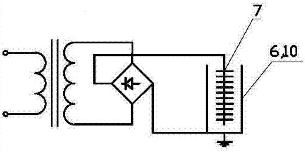
[0027] figure 1 It is the schematic diagram of the present invention, the negative end of the output of the high-voltage DC power transformer is electrically connected to the corona discharge electrode 7, the positive end of the output of the high-voltage DC power transformer is electrically connected to the dust collector such as the anode plate 6 or the housing 10 and grounded.

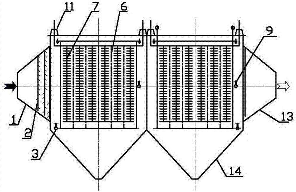
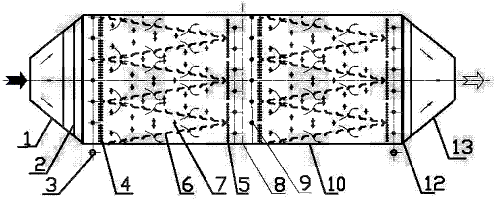
[0028] exist figure 2 Among them, for the overall structure of the present invention, the inlet distribution plate 2 is arranged in the inlet head 1, and the anode plate 6 is set to match the corona discharge electrode 7 in the Coulomb electric field, and the corona discharge electrode 7 is used at the top of the electric field with a high voltage The insulator 11 is electrically insulated from the shell 10, the corona discharge electrode 7 is vibrated by the middle or top cathode 9, the dust collection anode plate is vibrated by the bottom anode 3, the ash falls into the ash hopper 14 for collect...


PUM


Abstract

The invention relates to equipment for performing dust removal by utilizing static electricity. An inlet distribution plate is arranged in an inlet seal head; an anode plate is arranged in an electric field and is matched with a corona discharge electrode; the anode plate is arranged in a V shape; inlet ventilating boards are alternately arranged at the inlet end; the corona discharge electrode is electrically insulated from a shell on the top of the electric field by using a high voltage insulator; the corona discharge electrode is vibrated by adopting a middle or top cathode; the anode plate is vibrated by adopting a bottom anode; an ash bucket is arranged on the lower part of the electric field and is used for collecting the shaking dust; an outlet seal head and an outlet distribution plate are arranged at the outlet of the electric field; outlet ventilating boards are alternately arranged at the outlet end of the electric field. The equipment has the beneficial effects that secondary dust raising caused in the process of removing dust on the electric precipitation plate is overcome, and the problem that the collected dust escapes again is solved, so that the charged dust particles are not influenced by wind force. Moreover, the wind power is assisted to be forced to push to a dust collection plate, the bottleneck that the national emission standard cannot be reached due to high specific resistance trapping difficulty is broken through, and the overall construction cost is greatly saved.

Description

[0001] Field [0002] The invention relates to the electromechanical field, in particular to a device for dust removal using static electricity. Background technique [0003] The current known electrostatic precipitators have dust-collecting plates in the electric field, all of which are shielded flat plate structures. Parallel to the dust collection electrode, it is arranged in a straight line in the channel, so that many dust particles cannot approach the dust collection electrode due to high specific resistance or fast gas velocity, and the distance required by Coulomb’s law is very far, so that the wind force on the dust particles is greater than The Coulomb force of its charge causes a large number of dust particles to fly out of the electric field because it is too late or unable to reach the plate. In addition, the secondary flying of the collected dust due to rapping increases the dust discharge amount at the outlet, resulting in conventional It is difficult for flat-...

Claims


Application Information

Patent Timeline
Patent Type & Authority Applications(China)
IPC IPC(8): B03C3/04B03C3/47
Inventor 金烈水
Owner 金烈水
Why Eureka
Try Eureka