Bearing part hydrocarbon cleaning device

A technology for hydrocarbon cleaning and parts, applied in lighting and heating equipment, cleaning methods and utensils, cleaning methods using liquids, etc., can solve the problems of high design difficulty and complexity, reduce smoothness, parts damage, etc. Use fit and flexibility, reduced tightness requirements, simple delivery structure

Inactive Publication Date: 2014-06-25
ZHANGJIAGANG GANGWEI ULTRASONIC ELECTRONICS
View PDF9 Cites 18 Cited by
  • Summary
  • Abstract
  • Description
  • Claims
  • Application Information

AI Technical Summary

Problems solved by technology

[0002] Bearings are commonly used intermediate connecting parts in mechanical transmission structures. They are used to reduce the friction coefficient when the shaft structure is rotating. Clean and flawless, but in the production process of components, iron filings, grease and other impurities often remain on the surface of components, direct assembly and use will reduce the smoothness of use, and it is easy to damage the surface of internal parts, resulting in damage to parts
[0003] In the existing processing procedure, the processed bearing parts are put into the ultrasonic equipment and the hydrocarbon cleaning machine for cleaning treatment in order to eliminate the impurities on the surface of the parts, but this method requires manual movement of the items to be processed in each equipment part , the cleaning efficiency is relatively low; and there is another vacuum hydrocarbon cleaning machine, which installs ultrasonic, hydrocarbon cleaning and other equipment in a closed shell, so that the product can be cleaned in a vacuum environment, and the belt can be processed by the manipulator. Move between various equipments. Although this type of equipment realizes the automatic operation of the cleaning process with the processed parts and improves the processing efficiency, it needs to be equipped with additional vacuum equipment, and has high requirements for the sealing of the equipment, and uses manipulators as moving parts. The design difficulty and complexity of its structure are relatively high, and there are relatively large restrictions on the specifications of the parts to be processed, and the flexibility of use is insufficient.

Method used


Image

  • Bearing part hydrocarbon cleaning device
  • Bearing part hydrocarbon cleaning device

Examples


Embodiment Construction

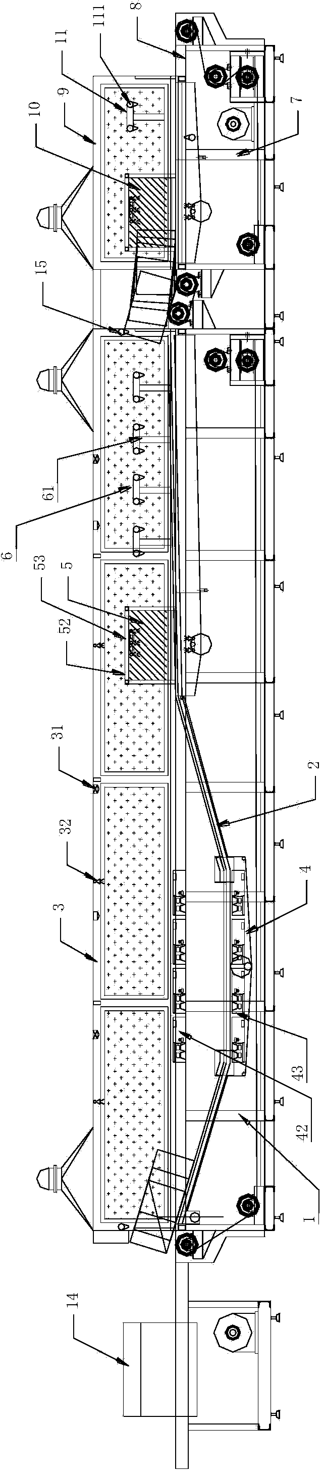
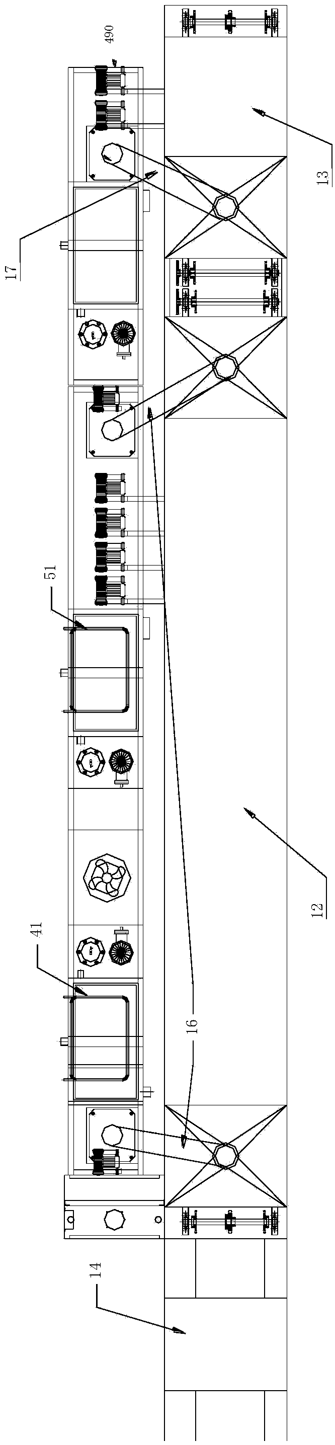
[0037] like Figure 1-2 As shown, the hydrocarbon cleaning equipment for bearing parts in this embodiment includes a main frame 1, the upper surface of the main frame 1 is provided with a main conveyor belt 2 extending along the upper surface of the main frame, and a main transparent cover is provided above the main frame 1 3. The main transparent cover 3 is provided with an ultrasonic cleaning assembly 4, a spray rinsing assembly 5, and a spray drying assembly 6 in sequence along the running direction of the main conveyor belt 2. The end of the main frame 1 is provided with a sub-frame 7. The auxiliary frame 7 is provided with a secondary conveyor belt 8 extending from the upper surface of the secondary frame 7, and a secondary transparent cover 9 is arranged above the secondary frame 8. In the secondary transparent cover 9, the running direction of the secondary conveyor belt 8 is successively provided with a spray protection device. Rust component 10 and antirust drying com...


PUM


Abstract

The invention relates to a bearing part cleaning device, in particular to a bearing part hydrocarbon cleaning device which comprises a main machine frame. The upper surface of the main machine frame is provided with a main conveying belt, a main transparent cover is arranged above the main machine frame, the inside of the main transparent cover is sequentially provided with an ultrasonic cleaning assembly, a spraying and rinsing assembly and a spraying and drying assembly, the tail end of the main machine frame is provided with an auxiliary machine frame, an auxiliary conveying belt is arranged on the auxiliary machine frame, an auxiliary transparent cover is arranged above the auxiliary machine frame, the inside of the auxiliary transparent cover is sequentially provided with a spraying rustproof assembly and a rustproof drying assembly, a vacuum ultrasonic cleaning tank is arranged in the ultrasonic cleaning assembly, a vacuum rinsing tank is arranged in the spraying and rinsing assembly, and a vacuum rustproof spraying tank is arranged on the spraying rustproof assembly, the main transparent cover and the auxiliary transparent cover are connected with a main air box and an auxiliary air box respectively, and the main air box and the auxiliary air box are used for absorbing mist. Manual work and automatic work are combined so that bearing part cleaning efficiency can be improved, requirements for sealing performance are lowered, and use adaptation and flexibility are improved.

Description

technical field [0001] The invention relates to a cleaning device for bearing parts, in particular to a hydrocarbon cleaning device for bearing parts. Background technique [0002] Bearings are commonly used intermediate connecting parts in mechanical transmission structures. They are used to reduce the friction coefficient when the shaft structure is rotating. Clean and flawless, and in the production process of components, iron filings, grease and other impurities often remain on the surface of the components. Direct assembly and use will reduce the smoothness of use, and it is easy to damage the surface of internal parts, resulting in damage to the parts. [0003] In the existing processing procedure, the processed bearing parts are put into the ultrasonic equipment and the hydrocarbon cleaning machine for cleaning treatment in order to eliminate the impurities on the surface of the parts, but this method requires manual movement of the items to be processed in each equip...

Claims


Application Information

Patent Timeline
Patent Type & Authority Applications(China)
IPC IPC(8): B08B3/12B08B3/02B08B3/08B08B13/00
CPCB08B3/12B08B3/02B08B3/08F26B21/00
Inventor 陆惠石
Owner ZHANGJIAGANG GANGWEI ULTRASONIC ELECTRONICS
Why Eureka
Try Eureka