Multicutter device of tile cutting machine

The technology of a tile excavator and a tool is applied in the field of processing devices of sintered NdFeB permanent magnet materials, which can solve the problems of low efficiency, affecting product qualification rate and yield, and low work efficiency.

Active Publication Date: 2014-06-25
CHALCO GUANGXI RARE EARTH DEV CO LTD
View PDF10 Cites 2 Cited by
  • Summary
  • Abstract
  • Description
  • Claims
  • Application Information

AI Technical Summary

Problems solved by technology

[0002] Sintered NdFeB is pressed by powder molding. In the molding of small-sized cylinders, due to the large aspect ratio, it is easy to break and crack during the molding process, and deformation and oxidation will also occur during the sintering process. , which seriously affects the product pass rate and yield
[0003] In order to solve the problem of small-sized cylinder forming, the manufacturer replaces direct forming with the method of machining the billet. After cutting with internal circle slicer, wire cutting and other equipment, it can be processed by square grinding machine and centerless grinding machine, which can effectively improve the The qualified recovery rate of small-sized cylinders, but the use of internal circle slicers requires repeated bonding, machine adjustment, cooking to remove adhesives, oil removal, etc., especially because it cannot be directly cut into circles, it needs to go through square grinding Round, centerless grinding and other processes, the process is cumbersome and requires high technology and low efficiency
Although wire cutting can be used to cut in place at one time, the speed is slow and the work efficiency is low, so it is difficult to mass produce
The tile removal machine can be used to install the corresponding specification blade to process, but the existing device can only install a single blade, which still cannot effectively improve work efficiency

Method used


Image

  • Multicutter device of tile cutting machine
  • Multicutter device of tile cutting machine
  • Multicutter device of tile cutting machine

Examples


Embodiment Construction

[0013] The present invention will be further described in detail below in conjunction with the accompanying drawings, so that those skilled in the art can implement it with reference to the description.

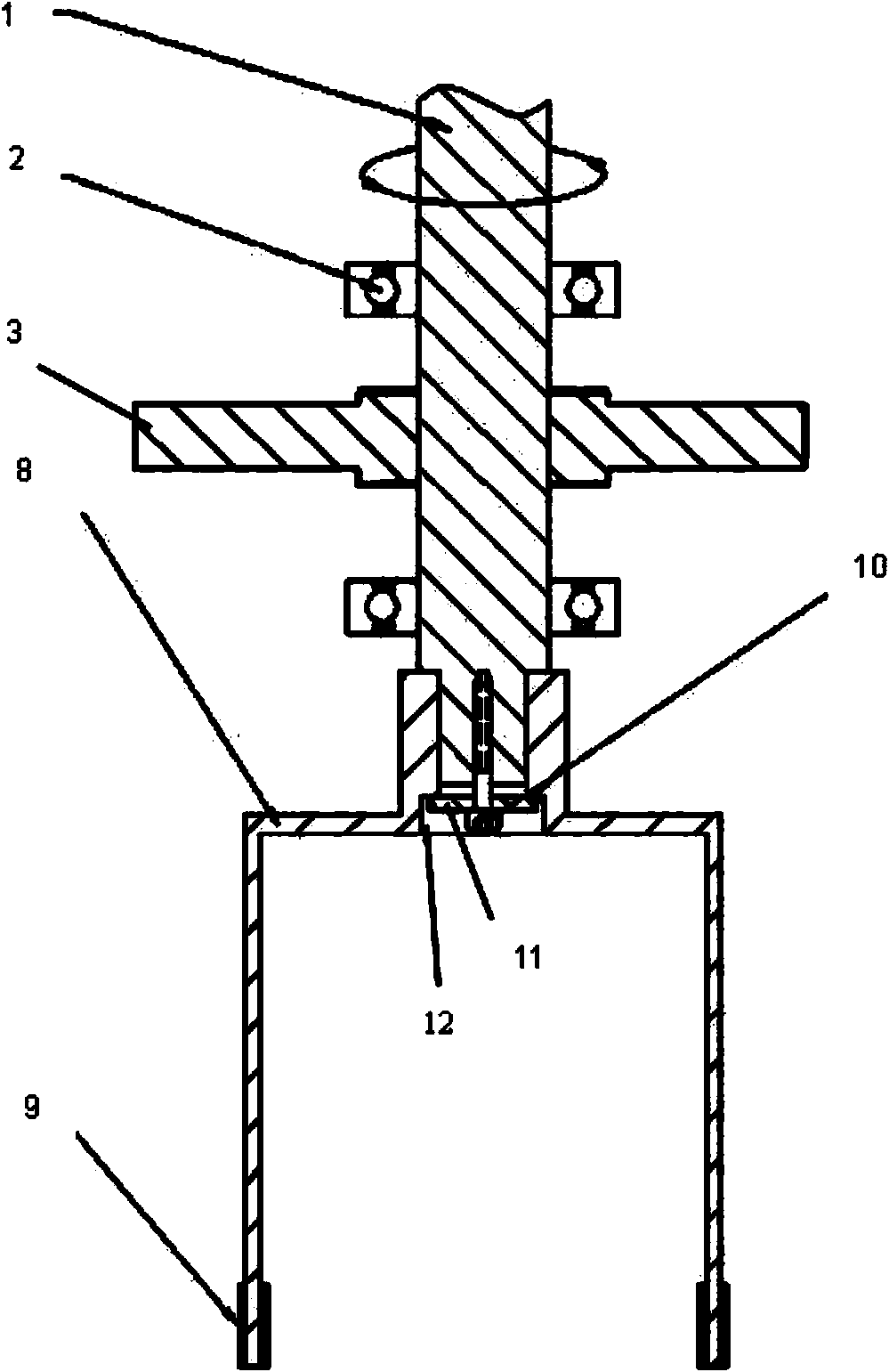
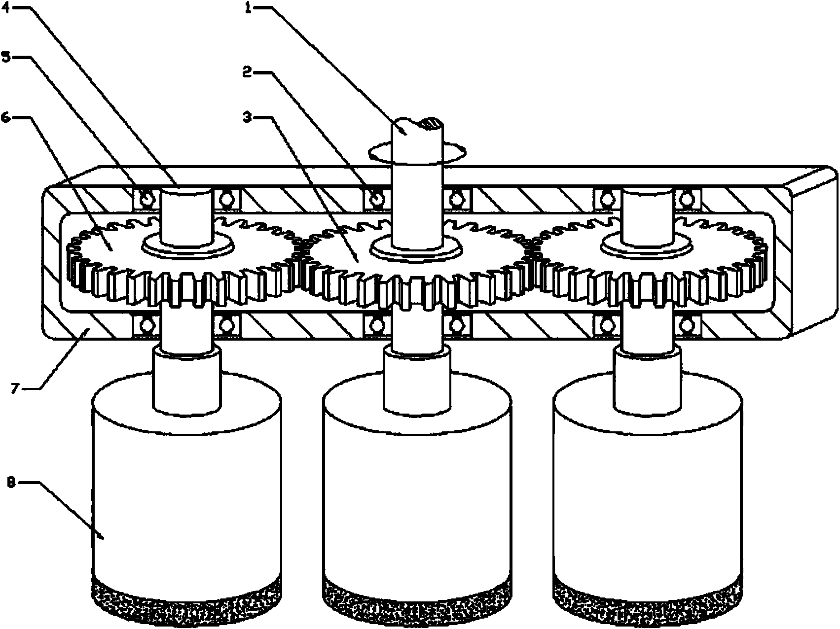
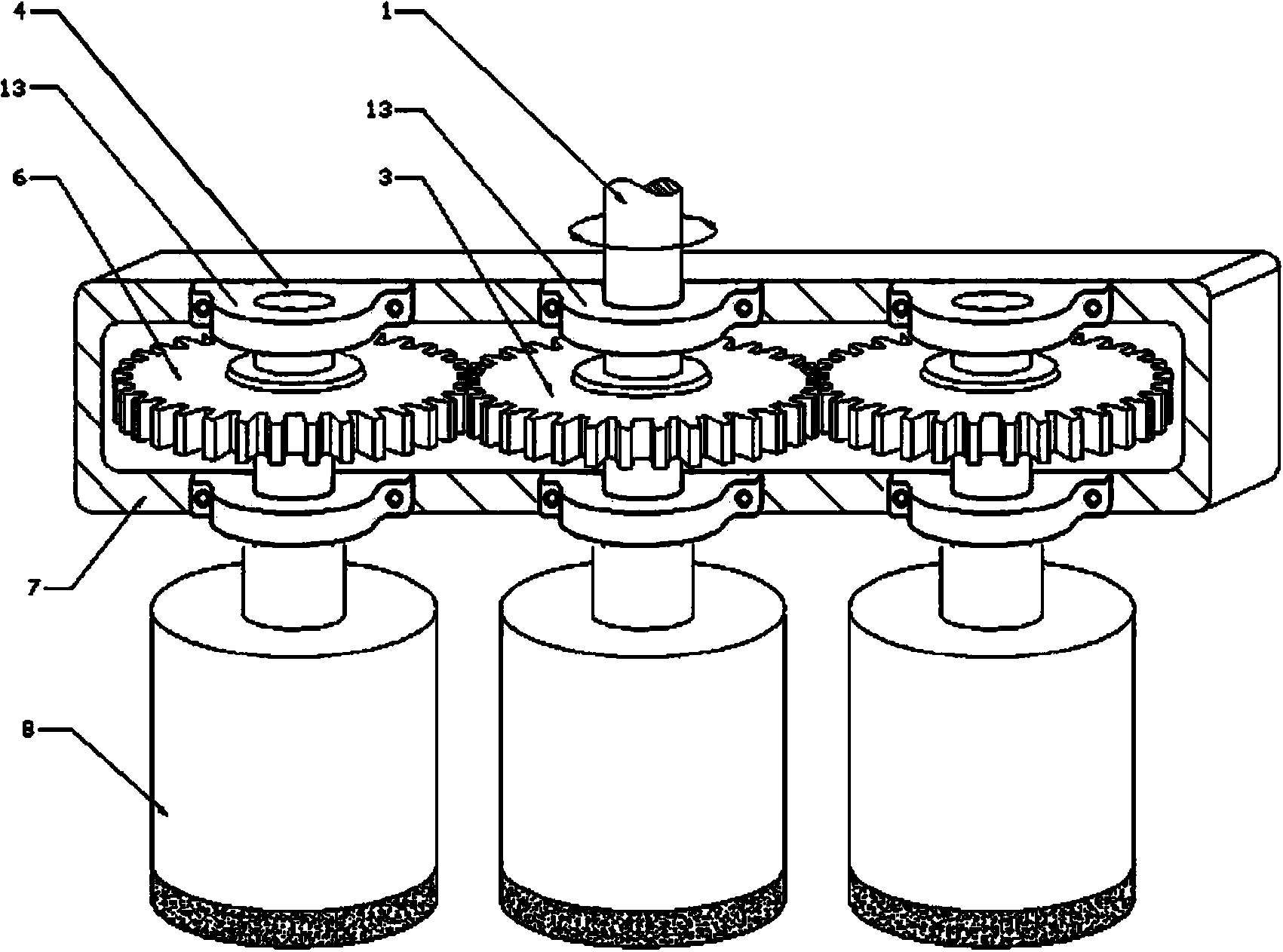
[0014] Such as figure 2 It can be seen that the present invention provides a multi-cutter device for a tile removal machine, which includes a removal tool 8, a bearing, a rotating shaft, a gear and a gearbox 7, and the rotating shaft is divided into a driving shaft 1 and a driven shaft 4. figure 1 It is a cross-sectional view of the drive shaft connection of the multi-cutter device of the tile removal machine according to the present invention. As can be seen from the figure, the removal tool 8 is a "convex" longitudinal section formed by combining two cylinders with different outer diameters. Glyph-shaped cylinder body, the upper cylinder body is provided with internal threads, and the interior of the connecting turning point with the lower cylinder body is provided with st...


PUM


Abstract

The invention discloses a multicutter device of a tile cutting machine. The multicutter device comprises multiple tile cutters, bearings, rotating shafts, gears and a gear box. The rotating shafts include a driving shaft and a driven shaft, the gears fixed on the rotating shafts are arranged inside the gear box and are mutually engaged with one another, the bearings sleeve the rotating shafts and the lower ends of the rotating shafts fully penetrate through holes in the lower side of the gear box, and the upper end of the driving shaft penetrates through holes in the upper side of the gear box, so that threaded parts of the rotating shaft are fully exposed out of the gear box to be connected with outer equipment conveniently, and the bearings are nested in a bearing cavity of the gear box. By the arrangement, the gears of the driving shaft drive the gears of the driven shaft to rotate to enable the tile cutters to run simultaneously, the tile cutters with different specifications can be connected according to actual needs to obtain neodymium-iron-boron products with different demands, the gears and the rotating shaft are protected through the gear box, generation of the multi-channel products can be realized on one production line by only one driving end of the tile cutting machine, production efficiency is high, cost is low and safety and practicability can be achieved.

Description

technical field [0001] The invention relates to a processing device for sintered NdFeB permanent magnet materials, in particular to a multi-cutter device for a tile removal machine. Background technique [0002] Sintered NdFeB is pressed by powder molding. In the molding of small-sized cylinders, due to the large aspect ratio, it is easy to break and crack during the molding process, and deformation and oxidation will also occur during the sintering process. , Seriously affect the product qualification rate and yield. [0003] In order to solve the problem of small-sized cylinder forming, the manufacturer replaces direct forming with the method of machining the billet. After cutting with internal circle slicer, wire cutting and other equipment, it can be processed by square grinding machine and centerless grinding machine, which can effectively improve the The qualified recovery rate of small-sized cylinders, but the use of internal circle slicers requires repeated bonding,...

Claims


Application Information

Patent Timeline
Patent Type & Authority Applications(China)
IPC IPC(8): B28D1/30
Inventor 黄伟超甘家毅黎翻谭海翔
Owner CHALCO GUANGXI RARE EARTH DEV CO LTD
Why Eureka
Try Eureka