Composite corrugated steel web box girder and construction technology thereof
A corrugated steel web and combined box technology, applied in bridges, bridge construction, erection/assembly of bridges, etc., can solve the problems of external cable anti-corrosion, excessive structural creep, and poor mechanical performance.
- Summary
- Abstract
- Description
- Claims
- Application Information
AI Technical Summary
Problems solved by technology
Method used
Image
Examples
Embodiment 1
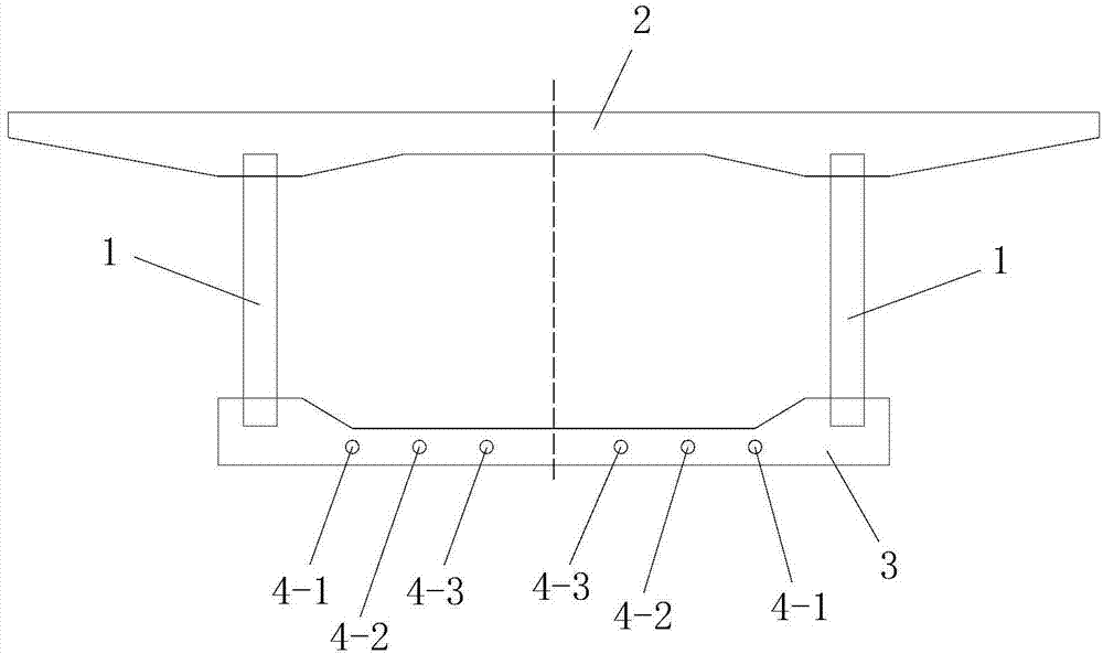
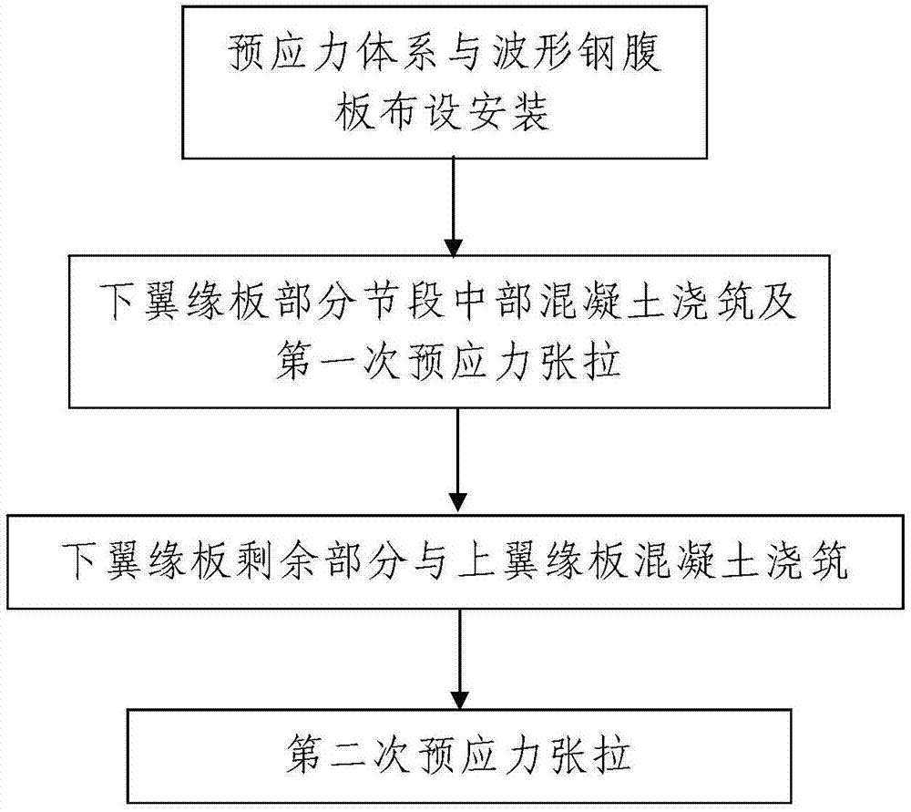
[0080] Such as figure 1 A corrugated steel web composite box girder shown includes a lower flange plate 3, an upper flange plate 2 located above the lower flange plate 3, and two symmetrical supports on the lower flange plate 3 and the upper flange plate 2 The corrugated steel web 1 between them, the upper flange plate 2 and the lower flange plate 3 are arranged horizontally along the longitudinal bridge direction of the bridge to be constructed, and the lower flange plate 3 is a cast-in-situ concrete plate and it is connected with the The upper flange plate 2 is fastened and connected as a whole through the two corrugated steel webs 1 , and the bottom of the corrugated steel web 1 and the lower flange plate 3 are fastened and connected through the lower shear connector. Such as figure 2 As shown, a prestressing system is arranged inside the lower flange plate 3 , and the prestressing system is located between two corrugated steel webs 1 . The prestressing system includes a...
Embodiment 2
[0116] In this embodiment, the construction of the corrugated steel web composite box girder is different from that in Embodiment 1 in that the middle prestressed structure is the second prestressed structure. combine Figure 7 , the second prestressing structure includes a plurality of fourth prestressing tendons 4-4 and a plurality of fifth prestressing tendons 4-5, a plurality of fourth prestressing tendons 4-4 and a plurality of fifth prestressing tendons The prestressed tendons 4-5 are all arranged on the same horizontal plane. The lower flange plate 3 is formed by connecting a front end segment, a rear end segment and a middle segment connected between the front end segment and the rear end segment, the front end segment, the middle The segments and the rear end segments are arranged along the length direction of the lower flange plate 3 from front to rear. The length L1 of the middle section is 0.6L-0.7L, and the fourth prestressed tendons 4-4 and the fifth prestresse...
Embodiment 3
[0139] In this example, if Figure 10 As shown, the difference between the constructed corrugated steel web composite box girder and that of Embodiment 1 is that the lower shear connector is a second shear connector structure. The second shear connection structure includes a plurality of first transverse connectors passing through the lower part of the corrugated steel web 1, and the plurality of first transverse connectors are all located on the same horizontal plane and are all along the bottom flange plate 3. The width direction is arranged, and the multiple first transverse connectors are arranged along the length direction of the lower flange plate 3 from front to back. A first through hole through which the transverse connecting piece passes. The lower part of the corrugated steel web 1 and the multiple first transverse connectors are poured into the lower flange plate 3 . The first transverse connecting piece is a PBL connecting piece or a steel bar, and the PBL conne...
PUM
 Abstract
Description
Claims
Application Information
 - R&D
- Intellectual Property
- Life Sciences
- Materials
- Tech Scout
- Unparalleled Data Quality
- Higher Quality Content
- 60% Fewer Hallucinations
Browse by: Latest US Patents, China's latest patents, Technical Efficacy Thesaurus, Application Domain, Technology Topic, Popular Technical Reports.
© 2025 PatSnap. All rights reserved.Legal|Privacy policy|Modern Slavery Act Transparency Statement|Sitemap|About US| Contact US: help@patsnap.com


