
turbine blade

A technology of turbine blades and blades, which is applied in the direction of blade support components, engine components, machines/engines, etc., can solve problems such as blocking the main flow channel, increasing the difficulty of heat transfer and cooling of turbine blade tips, and affecting the unsteadiness of the downstream flow field, etc.

Active Publication Date: 2016-05-04
AECC COMML AIRCRAFT ENGINE CO LTD
View PDF12 Cites 1 Cited by
  • Summary
  • Abstract
  • Description
  • Claims
  • Application Information

AI Technical Summary

Problems solved by technology

Among them, the leakage flow reduces the load on the blades, the leaked gas basically does no useful work, the leakage vortex produces dissipation and changes the gas outlet angle of the cascade, and at the same time, the leakage flow and the leakage vortex block the main flow channel, all of which increase the efficiency of the turbine. aerodynamic loss
In addition, the leakage flow and leakage vortex also increase the difficulty of heat transfer and cooling near the turbine blade tip, and greatly affect the unsteadiness of the downstream flow field.

Method used


Image

  • turbine blade
  • turbine blade
  • turbine blade

Examples


Embodiment Construction

[0038] In order to better understand the present invention, further detailed description will be given below in conjunction with specific embodiments, but it does not limit the present invention.

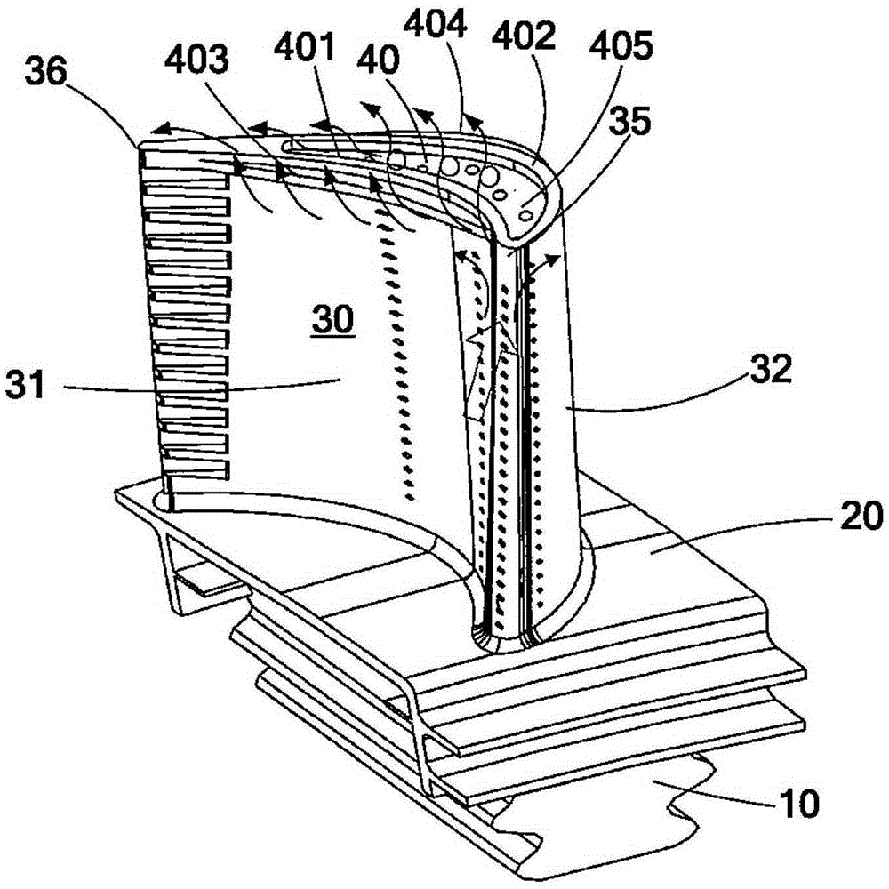
[0039] See first figure 1 , An exemplary turbine blade 30 for use in a gas turbine engine is shown. The blade is installed in the supporting rotor disk (not shown) through the edge plate 20 at the blade root and the supporting tenon 10. The supporting rotor disc supports a series of blades and the blades are circumferentially spaced apart from each other to form flow passages between the blades. During the operation of the turbine engine, the high temperature gas figure 1 As shown by the direction of the middle arrow, it flows to the blade leading edge 35 of the blade 30 and splits to flow to the pressure surface 31 and the suction surface 32. Since the relative pressure of the high-temperature fuel gas on the pressure surface 31 is higher than the pressure along the suction surface 3...


PUM


Abstract

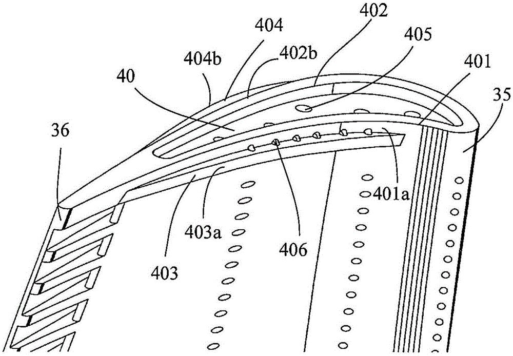
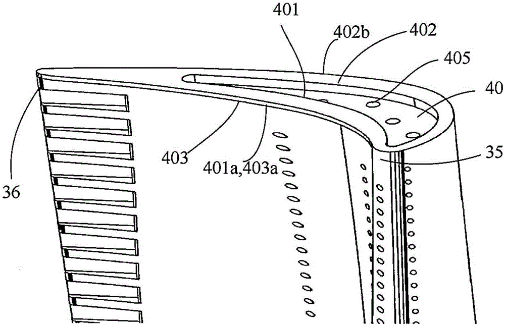
The invention provides a turbine blade which has a pressure face, a suction face, a blade top surface and at least one wing rib. The pressure face and the suction face are opposite and extend between a front edge and a tail edge of the blade, the blade top surface connecting the pressure face with the suction face is arranged at the pointed end of the blade, and the wing ribs extend from the pointed end of the blade and include at least one radial wing rib radially extending outwards from the blade top surface and / or at least one peripheral wing rib peripherally extending out from the pressure face and / or the suction face. The turbine blade with the wing ribs at the pointed end can beneficially combine respective advantages of the radial wing ribs and the peripheral wing ribs to realize effect of reducing leakage loss by different degrees.

Description

Technical field [0001] The present invention relates generally to gas turbine engines, and more specifically, to turbine blades therein. Background technique [0002] A gas turbine engine is a thermodynamic machine that converts the chemical energy of fuel into shaft work or aircraft propulsion work. Generally, air enters the engine from the intake duct, and is compressed by a fan and a low-pressure compressor, and the total temperature and total pressure of the air are increased; and then further compressed by the high-pressure compressor, the total temperature and total pressure of the air are further increased; Air enters the combustion chamber, mixes with fuel, and then burns to become high-temperature and high-pressure gas; the expansion of high-temperature and high-pressure gas drives high-pressure turbines and low-pressure turbines. Among them, the high-pressure turbine powers the upstream high-pressure compressor through the high-pressure shaft, and the low-pressure turbi...

Claims


Application Information

Patent Timeline
Patent Type & Authority Patents(China)
IPC IPC(8): F01D5/14F01D5/20
Inventor 蒋登宇赵亦凡刘帅强
Owner AECC COMML AIRCRAFT ENGINE CO LTD
Learn More