Detecting device and method for optical fiber oil-water interface

A detection device, optical fiber oil technology, applied in the direction of measuring device, lubrication indicator device, liquid level indicator, etc., can solve the problems of large deviation of detection results, complicated instruments, large longitudinal size of floating balls, etc., and achieve the goal of manufacturing and using Low cost, broad application prospects, and high measurement accuracy

Inactive Publication Date: 2014-06-25
WUHAN UNIV OF TECH
View PDF5 Cites 9 Cited by
  • Summary
  • Abstract
  • Description
  • Claims
  • Application Information

AI Technical Summary

Problems solved by technology

The existing oil-water interface measurement technology commonly used methods include capacitive, electrode, floating ball, ultrasonic detection and oil content detection. These methods have some defects when they are implemented. For example, in some explosion-proof requirements, power Capacitance and electrode detection methods do not meet explosion-proof requirements; ultrasonic detection and oil detection methods are affected by environmental temperature changes, and the detection results have large deviations, and the instruments used in this type of detection method are complicated, and the input and use costs are high; Due to the large longitudinal size of the floating ball, the ball detection method is difficult to accurately locate the specific position of the oil-water interface, especially when the oil-water interface is located at the bottom of the container, it is even impossible to measure

Method used


Image

  • Detecting device and method for optical fiber oil-water interface
  • Detecting device and method for optical fiber oil-water interface
  • Detecting device and method for optical fiber oil-water interface

Examples


Embodiment Construction

[0032] Below in conjunction with accompanying drawing, specific embodiment of the present invention is described in further detail:

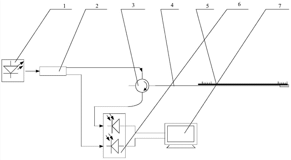
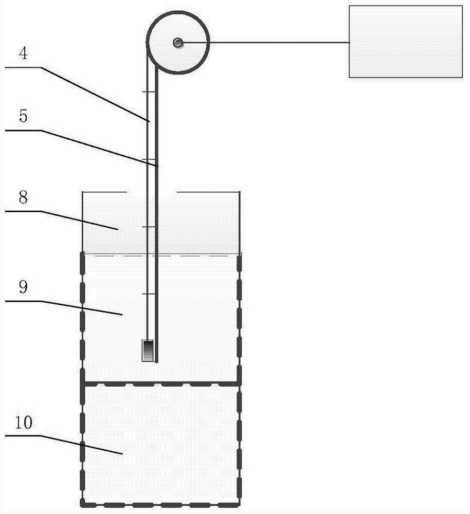
[0033] Such as figure 1 As shown, a detection device for an optical fiber oil-water interface of the present invention includes a narrow linewidth laser light source 1, an optical splitter 2, a circulator 3, an end-to-end pigtail 4, a length scale 5, a photodetector and signal processing with display module7. In this embodiment, the optical splitter 2 is a dual-path power divider, and the photodetector is a dual-optical-path photodetector 6 . A narrow linewidth laser source 1 is connected to an input end of an optical splitter 2 , and an output end of the optical splitter 2 is connected to a terminated pigtail 4 through a circulator 3 . The terminated pigtail 4 is preferably a G.652 optical fiber, and its free end is arranged side by side with the length scale 5 . For the convenience of reading, the end face of the free end of the pigtail 4 i...


PUM


Abstract

A detecting device for an optical fiber oil-water interface comprises a narrow-linewidth laser light source, a circulator, formed tail fibers, length ruler, a photoelectric detector and a signal processing and displaying module. The narrow-linewidth laser light source is connected with the forming end tail fibers through the circulator, the free end of the forming end tail fibers and the length ruler are arranged side by side, and a third port of the circulator is connected with the signal processing and displaying module through the photoelectric detector. The detecting method using the detecting device includes the steps that (1), before measurement, the power measuring value of the device in air is measured and recorded by using the tail end face of the free end of the forming end fibers; (2), the forming end optical fibers and the length ruler which are arranged side by side are immersed in oil-water mixed liquid to be detected and perpendicular to the liquid level, and when the power measuring value changes, reflective power and length ruler readings are recorded; (3), the forming end optical fibers and the length ruler are immersed further, and when the power value changes again, the reflective power and the length ruler readings are recorded; (4), the difference value of the length ruler readings in the step (2) and the step (3) is calculated and serves as the thickness of an oil layer.

Description

technical field [0001] The invention relates to the detection of the mixed liquid interface, in particular to a detection device and detection method for the optical fiber oil-water interface. Background technique [0002] Oil-water separation is widely used in petrochemical, shipbuilding and environmental protection industries. At present, the most widely used method is to use oil-water density difference layers for oil-water separation. In this process, the accurate measurement of the oil-water interface is the difficulty. The existing oil-water interface measurement technology commonly used methods include capacitive, electrode, floating ball, ultrasonic detection and oil content detection. These methods have some defects when they are implemented. For example, in some explosion-proof requirements, power Capacitance and electrode detection methods do not meet explosion-proof requirements; ultrasonic detection and oil detection methods are affected by environmental tempera...

Claims


Application Information

Patent Timeline
Patent Type & Authority Applications(China)
IPC IPC(8): G01F23/292
Inventor 郭会勇罗志会文泓桥余海湖胡宸源
Owner WUHAN UNIV OF TECH
Why Eureka
Try Eureka