Data-fusion-based reservoir bottom mud density detection method and system

A data fusion and sediment technology, which is applied to measuring devices, specific gravity measurement, instruments, etc., can solve the problem of inability to quantify the sediment density data at different locations, inability to infer the density characteristics of silted sediments from acoustic information, and deviation of sample detection results. Larger problems, to achieve the effect of high accuracy, strong penetration, and improved efficiency

Inactive Publication Date: 2014-06-25
YELLOW RIVER INST OF HYDRAULIC RES YELLOW RIVER CONSERVANCY COMMISSION
7 Cites 6 Cited by

AI-Extracted Technical Summary

Problems solved by technology

Sampling equipment such as grab type, box type, freezing type, and gravity type mainly have two major problems: the problem of disturbance to the sample during sampling and the problem of sample leakage during sampling, which will lead to large deviations in the test results of the samples taken and cannot be well tested. Represents the true properties of the sediment
[0004] Shallow strata profilers are used for acoustic detection, which is suitable for a wi...

Abstract

The invention discloses a data-fusion-based reservoir bottom mud density detection method and system. The system comprises a sampling device, a testing device and an analyzing device, wherein the sampling device is used for acquiring a bottom mud sample; the testing device is used for acquiring the relationship between the wave speed and depth of the bottom mud sample, the relationship between density and depth of the bottom mud sample, and the relationship between a reflection signal main frequency and the depth of the bottom mud sample; the analyzing device obtains the density of the bottom mud sample by analyzing and calculating the relationship between the density and the depth, the wave speed and the reflection signal main frequency; the testing device comprises a sub-bottom profiler, a transmitting transducer, a receiving transducer and a density testing instrument. The reservoir bottom ground layer reflection signal is recognized automatically by the method or the system provided by the invention; parameters of density and the like of a reservoir bottom ground layer are determined with combination of a low-disturbance sampling testing result, so that the bottom mud sampling is accurate, and the density detection is efficient.

Application Domain

Using subsonic/sonic/ultrasonic vibration meansSpecific gravity measurement

Technology Topic

Ground layerTest facility +4

Image

  • Data-fusion-based reservoir bottom mud density detection method and system
  • Data-fusion-based reservoir bottom mud density detection method and system
  • Data-fusion-based reservoir bottom mud density detection method and system

Examples

  • Experimental program(1)

Example Embodiment

[0030] The purpose of the present invention is based on the data processing method proposed by the data fusion technology, integrating low disturbance sampling equipment sampling detection data and shallow formation profiler sound wave detection data to form a set of high-efficiency reservoir sediment detection methods, so as to quickly obtain reservoir sediment Density and structure can provide basic data for more in-depth analysis and study of the law of water and sediment movement, and are of great significance for flood control and sediment discharge of deep-water reservoirs.
[0031] The technical solution of the present invention will be described in further detail below in conjunction with the accompanying drawings.
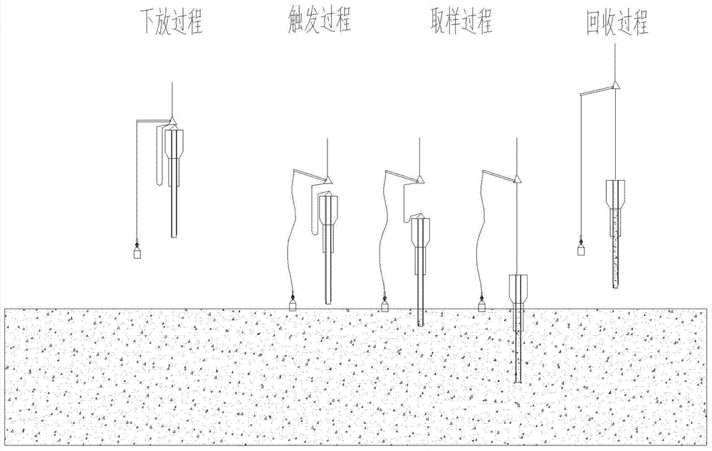
[0032] In recent years, the Yellow River Institute of Hydraulic Research has used the principle of fidelity sampling of deep-sea sediments to transform and develop a low-disturbance cylindrical deep reservoir sampling device based on gravity piston technology: Yang Yong, Zhang Qingxia, Chen Hao, Zheng Jun’s "Deep Water Reservoir Low Disturbance sampling equipment design and performance analysis [C]". Paper of the Fifth Yellow River International Forum, 2012.09; Yang Yong, Zheng Jun, Chen Hao, "Deepwater Reservoir Low Disturbance Sampling Equipment Mechanical Design". Water Resources and Hydropower Science and Technology Progress, 2012, 32 (S2):18-19: The designed sampling equipment has an inner diameter of 90mm and a tube length of 10m. The principle is: the main body of the sampling device falls freely and is inserted into the sludge under the action of its own weight and inertia. The lower end of the sampling device uses a claw spring structure to cut off and hold the sludge. The suction force generated by the piston offsets the balance of friction between the inner wall of the sampling device and the sample, so that the sampling device is full of low-disturbance sludge samples. Preliminary deep-water sampling tests conducted in the Sanmenxia reservoir area show that for soft riverbed silt, undisturbed column samples with a thickness of more than 3m can be obtained, but for hard silt, the friction angle of the soil particles is large and the silt is deposited. The compactness is large, resulting in unsatisfactory sampling effect.
[0033] The method of the present invention is to obtain a reservoir sediment sample (also called a test block) through a low-disturbance sampling device, and obtain the change rule of the physical properties of the sediment with depth through a shallow formation profiler test, and further conduct an acoustic test through a shallow formation profiler to obtain the sound The attenuation change function of the propagation characteristics is applied to the analysis of the test data of the shallow formation profile instrument to predict the existence of the weak reflection layer. In the absence of the reflection layer, the sediment physical properties conform to the in-situ test result prediction function.
[0034] The original sample obtained by the low-disturbance sampling device is a cylindrical sample with a diameter less than or equal to 90mm and a length less than or equal to 8m. The sample is installed in a liner tube. The liner tube is a transparent PC tube, which is easy to cut into sections and can be clearly distinguished and taken out with the naked eye. Sample layering, color and character.
[0035] The shallow formation profiler is used for the acoustic detection and scanning of the reservoir bottom mud. Its working frequency is 2-20kHz. It can detect the bottom mud thickness of the reservoir area from 0-100m and the working water depth range is 0-500m.
[0036] The reservoir sediment detection method based on data fusion mainly includes the following steps:
[0037] Step 1. The test vessel carries a shallow formation profiler to record the sonic data scanned on a survey line, convert the displayed topography of the reservoir bottom according to the sonic scan data, and select a relatively flat position on the survey line as the survey point for low disturbance sampling work ;
[0038] Step two, such as figure 1 As shown, the low-disturbance sampling equipment is mainly composed of diversion device, trigger device, sampling device and other parts. The acquisition of the test block is roughly divided into four stages: the lowering process, the triggering process, the sampling process and the recovery process. When the sampling device is lowered to a certain distance from the bottom of the river, the balance weight first touches the river bed, the lever loses balance, and the release is triggered. The mechanism moves, the main body of the sampling device falls freely and is inserted into the sludge under the action of its own weight and inertia. The lower end of the sampling device uses a claw spring structure to cut and hold the sludge. The suction force generated by the piston offsets the balance of friction between the inner wall of the sampling device and the sample, so that the sampling device is filled with low-disturbance sediment samples. The test vessel carries sampling equipment to perform low-disturbance sampling at the selected measuring points in the reservoir, and the samples taken are stored in the liner, and the liner is sealed and sent back to the laboratory;
[0039] Step three, such as figure 2 As shown, the thickness of the sediment sample is l c , Add water to the water tank, fix the transmitting transducer and the receiving transducer (the test block and the transducer are immersed in water during the test), the transmitting transducer transmits the signal, and the receiving time t of the receiving transducer is recorded 1 , Get the wave speed of water v w =l 1 /t 1. Place a sample between the transmitting transducer and the receiving transducer. On both sides of the sediment sample, use the penetration method to detect the transmission time t of the sound wave penetrating the test block 2 , The wave velocity of the test block is v c =l c /(t 2 -l 2 /v w -l 3 /v w ). The depth of the sediment sample taken is divided into n blocks, each of which has a thickness of dz. Perform acoustic testing of the sediment samples to obtain sound wave velocity data, and fit the wave velocity data to a function of depth z v 1 (z), the fitting function v 1 (z) at depth z>z 1 Expand the interval;
[0040] Step 4: Perform the density test of the sediment sample on the above sample by the density test instrument, and fit the density data to the function ρ of depth z 1 (z), set the fitting function at depth z>z 1 Expand the interval;
[0041] Step 5. Acoustic penetration method detects the absorption function of each sample: the transmitting transducer emits a linear frequency modulation signal (LFM) s lfm , The signal is consistent with the transmitted signal parameters of the shallow formation profiler, and the received signal is (I=1~n), the response function of the sample test block is fft is the Fourier transform. Since the reflected signal is two-way propagation, without considering the effect of reflection coefficient, the medium response function for two-way travel is: If there is a reflective layer at depth *dz, regardless of the reflection coefficient, the frequency domain function of the reflected signal is
[0042] s reflect k = fft ( s lfm ) · Π i = 1 k sd i c
[0043] take Main frequency. Get reflected signal The main frequency changes as a function of the depth z.
[0044] Received signal of shallow formation profiler s mea (t), s mea (t) Time length is T mea. Will s mea (t) Time domain windowing, T represents the length of windowing time, t 0 Represents time delay (0 0 mea ), take the Fourier transform fft() of the windowed signal, and get the dominant frequency as f, and the corresponding depth of the signal satisfies the function.
[0045] Step 6. Increase from 0 to, if () does not satisfy the function f, the sand density at the depth is, and the longitudinal wave velocity is; if () satisfies the function f, it is judged that there is a reflection layer at the depth.
[0046] The steps three to six can be standardized by combining computer programs with computer hardware, effectively popularizing the above methods.
[0047] Compared with the prior art, the positive effects of the present invention are:
[0048] (1) The use of low-disturbance sampling equipment can obtain long undisturbed samples of bottom mud in the reservoir area. Compared with drilling exploration sampling, gravity sampling, and grab sampling, it improves efficiency, reduces costs, and reduces sampling work. The impact of disturbances can obtain more accurate physical properties of sediments.
[0049] (2) Use shallow formation profiler to scan the sound waves, the sound wave emission frequency is low, the generated sound wave electric pulse energy is larger, it has strong penetrating power, can effectively penetrate the stratum tens of meters under water, and the detection efficiency is high , High accuracy.
[0050] (3) Obtain the data of the wave velocity and density of the bottom mud in the reservoir area by using the indoor experiment, fit the two kinds of data to different function curves, find out the correlation between the two, and expand the function reasonably, so that the depth of the sample can be derived Below are the density characteristics of the sediments to obtain the density characteristics parameters of the sediments at a deeper depth in the reservoir area.
[0051] (4) Use the acoustic data scanned by the shallow formation profiler to compare with the established curve, and use the signal spectrum characteristics to quickly identify the formation parameters, which is conducive to the analysis of the bottom mud bedding in the reservoir area.
[0052] (5) Form a set of high-efficiency reservoir sediment density detection methods. This method is applicable to a wide range of reservoirs and can be popularized and applied to many other reservoirs. It improves the efficiency of reservoir sediment detection and provides important basic data for reservoir management and development.

PUM

PropertyMeasurementUnit
The inside diameter of90.0mm
Tube chief10.0m
Thickness0.0 ~ 100.0m

Description & Claims & Application Information

We can also present the details of the Description, Claims and Application information to help users get a comprehensive understanding of the technical details of the patent, such as background art, summary of invention, brief description of drawings, description of embodiments, and other original content. On the other hand, users can also determine the specific scope of protection of the technology through the list of claims; as well as understand the changes in the life cycle of the technology with the presentation of the patent timeline. Login to view more.

Similar technology patents

Systems and methods for notifying multiple hosts from an industrial controller

ActiveUS8150959B1reusable block of code very difficultimprove efficiency
Owner:ROCKWELL AUTOMATION TECH

MIMO-OFDM transmitter

InactiveUS20070253504A1improve efficiencyreduce time
Owner:FUJITSU LTD

Systems and methods for providing treatment planning

InactiveUS20050182654A1high quality of careimprove efficiency
Owner:ALIGN TECH

Classification and recommendation of technical efficacy words

  • Improve efficiency
  • low cost

System and method for transmitting wireless digital service signals via power transmission lines

ActiveUS7929940B1reduce bandwidth requirementlow cost
Owner:NEXTEL COMMUNICATIONS

Plastic waveguide-fed horn antenna

InactiveUS20100214185A1low cost
Owner:RGT UNIV OF CALIFORNIA

System and method for determination of position

InactiveUS20090149202A1low costreduce requirement
Owner:STEELE CHRISTIAN

Adaptive antenna optimization network

InactiveUS6961368B2low costminimal space
Owner:ERICSSON INC
Why Eureka
Try Eureka