Novel topology loop for measuring breaker loop resistance and measuring method of novel topology loop

A technology for loop resistance and resistance measurement, which is applied in the direction of measuring electrical variables, measuring resistance/reactance/impedance, measuring devices, etc. It can solve the problems of long power-on time, burnt oxide film, large volume and weight, etc., to ensure measurement accuracy and stability, reduced volume and weight, simple loop structure

Inactive Publication Date: 2014-06-25
STATE GRID CORP OF CHINA +2
View PDF4 Cites 4 Cited by
  • Summary
  • Abstract
  • Description
  • Claims
  • Application Information

AI Technical Summary

Problems solved by technology

[0005] When using the voltage drop method of a large constant current source and the micro-ohmmeter method to measure the circuit breaker circuit resistance, although the sensitivity requirements of the measuring instrument can be reduced, and the oxide film on the contact can be easily burned, but due to the measurement, If the power-on time is long, the temperature of the measured resistance will rise accordingly, which will have a great impact on the measurement results and reduce the measurement accuracy.
In addition, most of the above-mentioned instruments are bulky and heavy, and are not convenient for portability and on-site testing applications.
Some scholars have proposed to use the pulse current method to measure the circuit breaker circuit resistance, but the existing test circuit topology and control methods are relatively complicated
[0006] To sum up, the existing methods for measuring circuit breaker circuit resistance are not ideal, and necessary improvements and designs must be made.

Method used


Image

  • Novel topology loop for measuring breaker loop resistance and measuring method of novel topology loop

Examples


Embodiment Construction

[0016] In order to make the technical means, creative features, goals and effects of the present invention realized easily

[0017] For clear understanding, the present invention will be further described below in conjunction with specific embodiments.

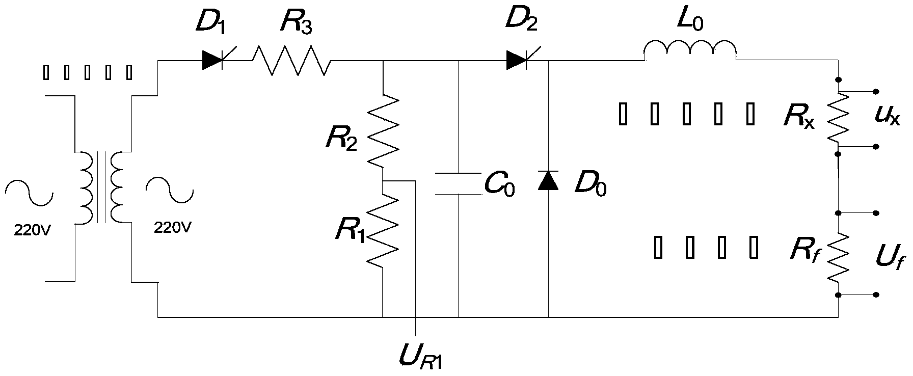
[0018] see figure 1 , the present embodiment is a novel topological circuit for measuring circuit breaker circuit resistance, which includes four parts: capacitor charging circuit, capacitor discharging circuit, measurement circuit, and thyristor control circuit, which specifically includes a test power supply, an isolation transformer connected to the test power supply, Current limiting resistor R 3 , Capacitor C 0 , Oscillating inductance L 0 , circuit breaker resistance R x , Measuring resistance R 1 , The measured circuit breaker resistance R X and the standard resistor R f . The main measurement parameter of the present invention is the circuit breaker resistance R x , standard resistance R f The voltage across ...


PUM


Abstract

The invention relates to a novel topology loop for measuring breaker loop resistance and a measuring method of the novel topology loop. The novel topology circuit comprises a capacitor charging loop, a capacitor discharging loop, a measuring loop and a thyristor control loop. The novel topology circuit specially comprises a test power source, an isolation transformer, a current-limiting resistor, a capacitor, a vibration inductor, a breaker resistor, a measuring resistor, a detected breaker resistor and a standard resistor, wherein the isolation transformer is connected with the test power source. The method comprises the steps that the test power source charges the capacitor, and the thyristor control loop controls the connection and disconnection of the charging and discharging loop; the capacitor carries out discharging on an RLC loop composed of the vibration inductor, the detected breaker resistor and the standard resistor, a pulse current source no less than 100 A is generated, the voltage at the two ends of the detected breaker and the standard resistor is measured to be calculated, and the resistance value of the detected breaker loop is obtained through calculation. The novel topology loop is simple in structure, easy to achieve and good in economical efficiency, the detecting device becomes smaller while the measuring precision is guaranteed, and the novel topology circuit is convenient to carry.

Description

technical field [0001] The invention relates to a topological circuit for measuring circuit breaker circuit resistance and a measuring method thereof, belonging to the field of electrical testing of electric power systems. Background technique [0002] The circuit breaker circuit resistance is mainly composed of three parts: the resistance of the conductive material itself, the fixed connection resistance and the contact resistance of the movable connection. Among them, the resistance value of the first two parts is generally constant, and the movable part is composed of dynamic and static contacts. The contact resistance value is related to its contact mode, contact pressure and contact surface state, and often changes greatly. Accurate measurement of contact resistance is of great significance for correctly evaluating the performance status of circuit breakers. [0003] At present, the commonly used method for measuring resistance in the laboratory is to use a DC double-a...

Claims


Application Information

Patent Timeline
Patent Type & Authority Applications(China)
IPC IPC(8): G01R27/14
Inventor 孙秋芹刘洋赵科马勇周志成陶风波
Owner STATE GRID CORP OF CHINA
Why Eureka
Try Eureka