Full bridge uncontrolled rectifier fault diagnosis method based on insulation monitoring

A technology of insulation monitoring and fault diagnosis, which is applied in the direction of instruments, measuring electronics, and measuring devices. It can solve problems such as system failure, high cost of rectifiers, and small faulty diodes, and achieve strong operability, increased complexity, and low cost. Effect

Inactive Publication Date: 2014-06-25
ARMY ENG UNIV OF PLA
View PDF4 Cites 10 Cited by
  • Summary
  • Abstract
  • Description
  • Claims
  • Application Information

AI Technical Summary

Problems solved by technology

The reverse breakdown of the diode itself or the destruction of the insulating layer of the bridge arm will cause a short circuit of the diode, resulting in a rapid rise in current and a steep drop in conduction voltage drop. In severe cases, the equipment will be damaged and the system will be paralyzed; Poor wiring or over-current burning will cause the diode to open circuit, which may cause the current of other diodes to exceed the limit, the output DC voltage ripple will increase, and affect the normal operation of the device; these are the most common faults of the rectifier and harm
Especially for small, low-power rectifiers, it is of little significance to indicate the range of faulty diodes, because low-power diodes are cheap, and the rectifier bridge is made modular, and there is no need to disassemble and replace the diodes; but once the diodes are short-circuited or The harm caused by an open-circuit fault is far higher than the cost of the rectifier. Therefore, within the scope of the IT system, if you can use its own IMD to diagnose the faulty rectifier and remind the maintenance personnel to deal with the rectifier in time, it will be possible for the rectifier. The convenience of maintenance work is also very important for ensuring the safety and power quality of the entire system

Method used


Image

  • Full bridge uncontrolled rectifier fault diagnosis method based on insulation monitoring
  • Full bridge uncontrolled rectifier fault diagnosis method based on insulation monitoring
  • Full bridge uncontrolled rectifier fault diagnosis method based on insulation monitoring

Examples


Embodiment Construction

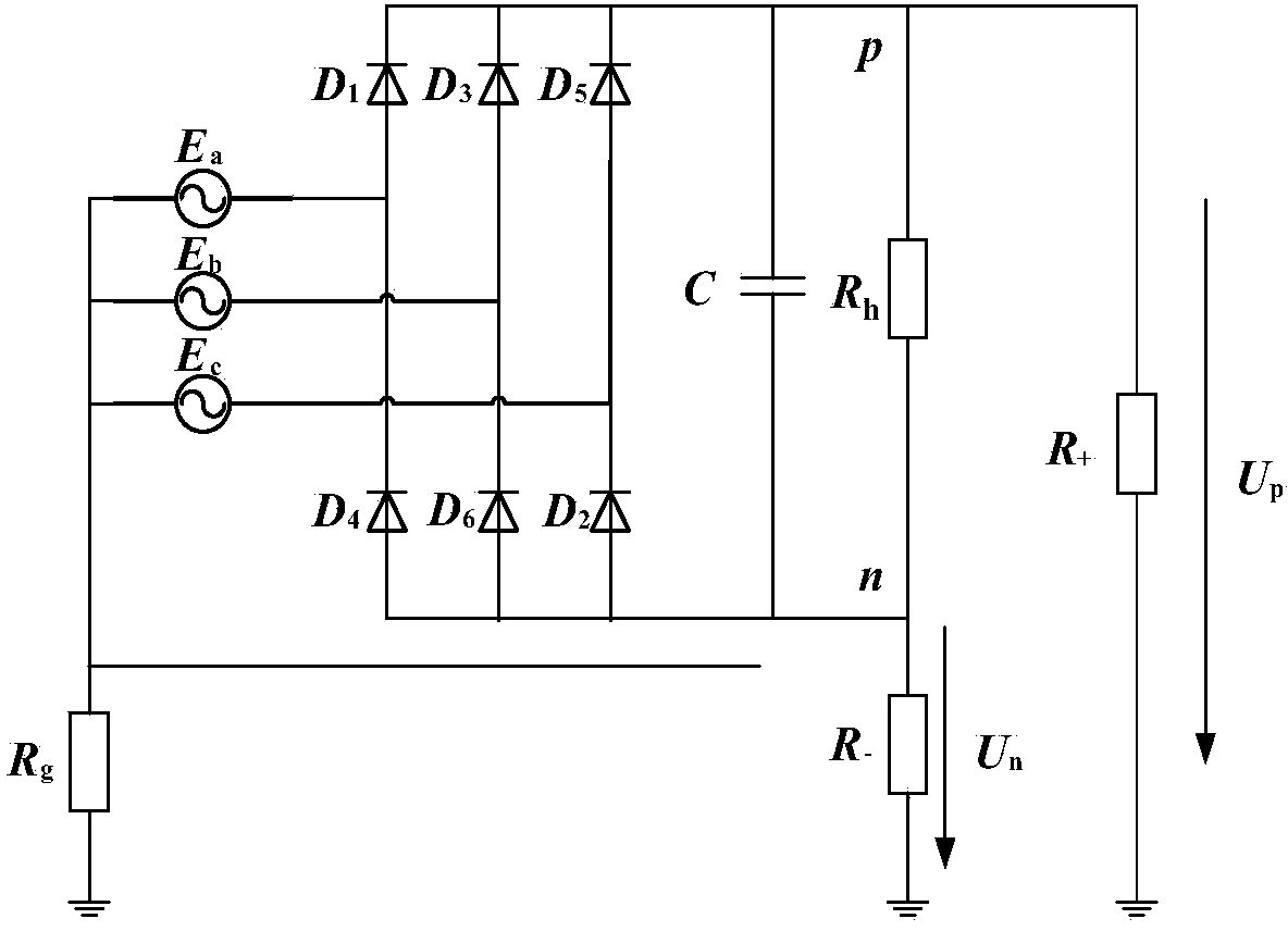
[0039] Such as figure 1 As shown, it is a circuit diagram of an IT system with a three-phase bridge uncontrolled rectifier. According to the switching function of the uncontrolled rectifier, the common cathode or common anode diodes are respectively turned on in one cycle, and the conduction of each diode occupies The duty ratio is one-third of a cycle. Using this feature, three diodes with a common cathode can be equivalent to a diode, and a diode with a common anode can also be equivalent to a diode. At the same time, the three-phase power supply can be The upper and lower bridge arms are equivalent, respectively E p ,E n , and finally the R h , R + , R - The three delta-connected resistors, through △-Y transformation, become by R p , R n , R l composed of Y-connected resistors.

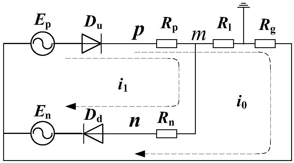
[0040] Such as figure 2 Shown, D u is the equivalent common cathode diode, D d is an equivalent common anode diode, and the equivalent resistance and equivalent power supply in the figu...


PUM


Abstract

The invention provides a full bridge uncontrolled rectifier fault diagnosis method based on insulation monitoring. Insulation resistance Rt of a system under normal operation conditions is measured first; the positive electrode and the negative electrode of an IMD injecting source based on a direct current injection method are connected with a neutral line and the ground respectively, and a system insulation monitoring value Rf when IMD forward injection is carried out is obtained through measurement; the direction of IMD injection signals is changed, the positive electrode and the negative electrode of the IMD injecting source are connected with the ground and the neutral line respectively, and the insulation monitoring value Rr when the IMD reverse injection is carried out can be measured; if the Rf or the Rr is not equal to the Rt, the system enters a fault diagnosis process, the real insulation resistance Rm of the system is calculated by using the collected Rf and the Rr, the Rm is then compared with the insulation resistance Rt under the normal operation conditions of the system, and whether the changing of the insulation resistance is caused by fault of a rectifier is obtained.

Description

technical field [0001] The invention relates to a fault diagnosis method for an uncontrolled rectifier in an IT power distribution system, in particular to a fault diagnosis method for a full-bridge uncontrolled rectifier based on insulation monitoring. Background technique [0002] The failure of the rectifier mainly refers to the failure of the diode in the rectifier bridge. The reverse breakdown of the diode itself or the destruction of the insulating layer of the bridge arm will cause a short circuit of the diode, resulting in a rapid rise in current and a steep drop in conduction voltage drop. In severe cases, the equipment will be damaged and the system will be paralyzed; Poor wiring or over-current burning will cause the diode to open circuit, which may cause the current of other diodes to exceed the limit, the output DC voltage ripple will increase, and affect the normal operation of the device; these are the most common faults of the rectifier and harm. [0003] N...

Claims


Application Information

Patent Timeline
Patent Type & Authority Applications(China)
IPC IPC(8): G01R31/00
Inventor 王金全李乾叶小松邢鸣徐晔赵锦成胡亚超李建科侯朋飞
Owner ARMY ENG UNIV OF PLA
Why Eureka
Try Eureka