Faraday rotation reflection mirror and optical fiber interferometer

A technology of Faraday rotation, fiber optic interferometer, applied in the field of fiber optic interferometer

Active Publication Date: 2014-06-25
ZHUHAI FTZ OPLINK COMM
View PDF6 Cites 15 Cited by
  • Summary
  • Abstract
  • Description
  • Claims
  • Application Information

AI Technical Summary

Problems solved by technology

[0011] Moreover, at different temperatures, the central wavelength of the Faraday rotator 12 will change, therefore, for a light beam with a fixed wavelength, it cannot be guaranteed to be at different temperatures , the fiber optic interferometer can work normally, which greatly limits the scope of use of the fiber optic interferometer

Method used


Image

  • Faraday rotation reflection mirror and optical fiber interferometer
  • Faraday rotation reflection mirror and optical fiber interferometer
  • Faraday rotation reflection mirror and optical fiber interferometer

Examples


no. 1 example

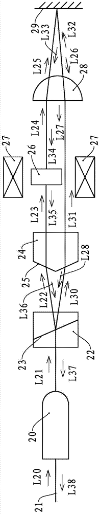
[0037] see image 3 , the Faraday rotating mirror of the present embodiment has a single-fiber collimator 20, and the output end of the single-fiber collimator 20 is provided with a polarization light-splitting light-combining device, and the polarization light-splitting light-combining device of the present embodiment consists of a Wollaston prism 22 And roof prism 24 constitutes. The Wollaston prism 22 is located at the output end of the single fiber collimator 20, and a beam splitter 23 is provided inside it. After the light beam of any polarization state enters the Wollaston prism 22, the polarization states are perpendicular to each other on the beam splitter 23. The two beams of light exit from the exit surface of the Wollaston prism 22.

[0038] The roof prism 24 is located on the exit surface of the Wollaston prism 22 , and its roof surface 25 faces the exit end of the Wollaston prism 22 . After the two light beams emitted from the Wollaston prism 22 are incident on ...

no. 2 example

[0050] see Figure 5 and Figure 6 , the Faraday rotating reflector of the present embodiment has double-fiber collimator 30, the polarization light-splitting light-combining device that is positioned at double-fiber collimator 30 exit ends, and the polarization light-splitting light-combining device of the present embodiment is made of Wollaston prism 33 and roof The prism 35 is constituted, the Wollaston prism 33 has a dichroic surface 34 , and the roof surface 36 of the roof prism 35 faces the Wollaston prism 33 .

[0051] The outgoing end of the roof prism 35 is provided with a Faraday rotator 37 , and the outer side of the Faraday rotator 37 is provided with a magnetic field generating device 38 , and the Faraday rotator 37 is located on an outgoing optical path of the roof prism 35 . The outgoing end of the Faraday rotator 37 is provided with a focusing lens 39 , and the outgoing end of the focusing lens 39 is provided with a reflective mirror 40 .

[0052] The optical...

no. 3 example

[0058] see Figure 7 , the present embodiment has a single fiber collimator 41, a birefringent crystal 43 positioned at the exit end of the single fiber collimator 41, the exit end of the birefringence crystal 43 is provided with a Faraday rotator 44, and the exit end of the Faraday rotator 44 is provided with a focusing Lens 46 , reflective mirror 47 is provided at the output end of the focusing lens 46 , and the reflective surface of the reflecting mirror 47 faces the focusing lens 46 and is located at the focal point of the focusing lens 46 . In this embodiment, the birefringent crystal 43 is a polarization splitting and combining device for splitting or combining light beams. The birefringent crystal 43 can be a discrete birefringent crystal, or a composite birefringent crystal. In addition, the Faraday rotator 44 is located on one of the outgoing light paths of the birefringent crystal 43 , and a magnetic field generating device 45 is provided outside it.

[0059] The o...


PUM


Abstract

The invention provides a Faraday rotation reflection mirror and an optical fiber interferometer. The Faraday rotation reflection mirror comprises a collimator, wherein a Faraday rotator is arranged at the emergence end of the collimator, and a reflection mirror is arranged at the emergence end of the Faraday rotator. A polarizing beam-splitting beam-combining device are arranged between the emergence end of the collimator and the Faraday rotator, the Faraday rotator is located on an emergence optical path of the polarizing beam-splitting beam-combining device, light beams pass through the Faraday rotator and then rotate for 90 degrees in a polarization state, and a focusing lens is arranged between the emergence end of the Faraday rotator and the reflection mirror. The optical fiber interferometer is provided with two interference arms, wherein each interference arm is provided with the Faraday rotation reflection mirror. The Faraday rotation reflection mirror is suitable for the optical fiber interferometer which is large in wavelength range, insensitive to temperature change and high in signal to noise ratio.

Description

technical field [0001] The invention relates to an optical device used in an optical fiber measurement system, in particular to a Faraday rotating reflector and an optical fiber interferometer with the Faraday rotating reflector. Background technique [0002] Various optical instruments are often used in modern optical communication systems, Michelson fiber interferometer is a common optical instrument. Michelson fiber optic interferometer uses optical fiber to realize double-beam interference of light. It is composed of optical fiber and optical fiber devices instead of free space components such as splitters and lenses. It has small size, light weight, anti-electromagnetic interference, anti-corrosion, and high sensitivity. High, wide measurement bandwidth, detection electronics and sensors can be far apart. The fiber optic interferometer adopts optical interference technology, and its measurement accuracy is higher than that of ordinary fiber optic sensors. Therefore, th...

Claims


Application Information

Patent Timeline
Patent Type & Authority Applications(China)
IPC IPC(8): G02B27/28G02F1/09
Inventor 陈达鑫李林虎周风晴赵泽雄毛宏伟乔金元
Owner ZHUHAI FTZ OPLINK COMM
Why Eureka
Try Eureka