Passive direction-finder antenna array of phase interferometer and phase interferometer

A phase interferometer and direction-finding antenna technology, which is applied in the field of direction-finding systems, can solve the problems of complex structure, complex structure, and bulky size of direction-finding antenna arrays, and achieve the effects of simple structure, high test sensitivity, and improved integrated structure

Active Publication Date: 2014-06-25
GUANGZHOU HAIGE COMM GRP INC
View PDF3 Cites 27 Cited by
  • Summary
  • Abstract
  • Description
  • Claims
  • Application Information

AI Technical Summary

Problems solved by technology

The traditional active direction-finding antenna array is limited by the working bandwidth of the active circuit and the consistency requirements of the antenna electrical performance index in the wide frequency band. It usually adopts a divided frequency band design. Although its volume can be made relatively small, the structure is complex and the cost is high; Most of the existing passive direction-finding antenna arr

Method used


Image

  • Passive direction-finder antenna array of phase interferometer and phase interferometer
  • Passive direction-finder antenna array of phase interferometer and phase interferometer
  • Passive direction-finder antenna array of phase interferometer and phase interferometer

Examples


Embodiment

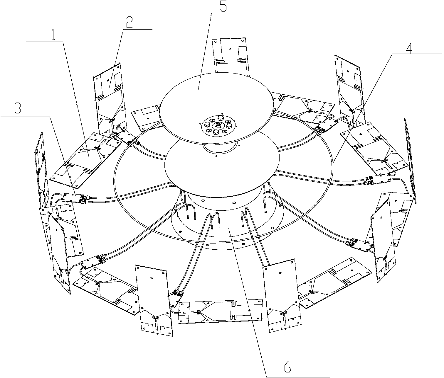
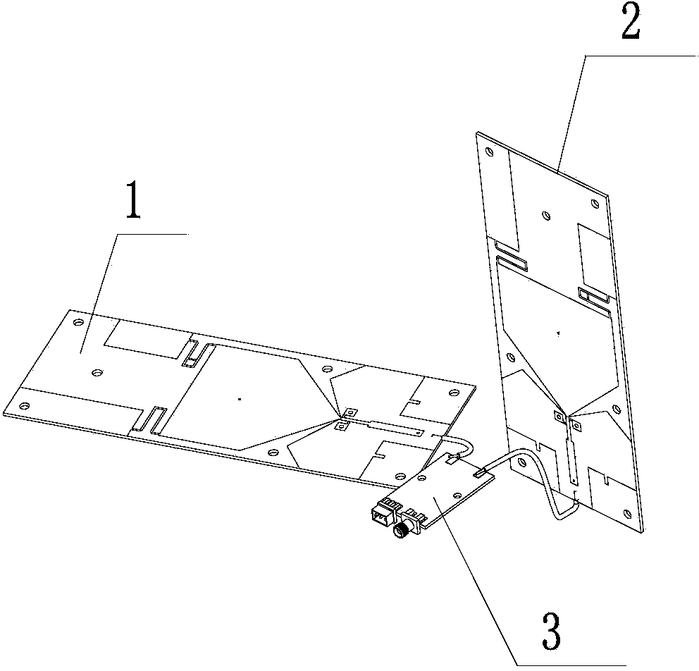
[0035] Such as figure 1 As shown, this embodiment discloses a passive direction-finding antenna array of a phase interferometer, which is divided into three layers from outside to inside: the first layer is a circular antenna array, and the circular antenna array is composed of nine dipoles Composed of omnidirectional antenna elements; nine dual-polarized omnidirectional antenna elements are arranged on a circle; each dual-polarized omnidirectional antenna element includes a horizontally polarized oscillator 1 and a vertically polarized oscillator 2, where The horizontally polarized vibrator and the vertically polarized vibrator are arranged adjacent to each other on the circumference. In this embodiment, the horizontally polarized vibrator 1 and the vertically polarized vibrator 2 in each dual-polarized omnidirectional antenna array element are respectively connected to the same polarization selection The two input ends of the output matching board 3 are connected respectivel...

Embodiment 2

[0053] This embodiment discloses a passive direction-finding antenna array for a phase interferometer. The difference between this embodiment and Embodiment 1 is that the dual-polarized omnidirectional antenna elements of the circular antenna array in this embodiment are divided into There are multiple groups, and each group contains more than two dual-polarized omnidirectional antenna elements, and each group of dual-polarized omnidirectional antenna elements is respectively connected to a multi-select one antenna switch, and each group of circular antenna arrays is dual-polarized omnidirectional The signals received by the antenna array elements are switched by multiple-choice antenna switches connected to each group of dual-polarized omnidirectional antenna array elements, and then enter the sampling channels of the phase interferometer receiver respectively. The passive direction-finding antenna array in this embodiment is suitable for a phase interferometer with more than ...


PUM

PropertyMeasurementUnit
Lengthaaaaaaaaaa

Abstract

The invention discloses a passive direction-finder antenna array of a phase interferometer and the phase interferometer. The passive direction-finder antenna array comprises three layers from inside to outside. The first layer is a circular antenna array composed of a plurality of dual-polarization omnidirectional antenna array elements which are arranged on a circumference, each dual-polarization omnidirectional antenna array element comprises a horizontal polarization oscillator and a perpendicular polarization oscillator and is connected with one-out-multiple antenna switch through a polarization choice output matching board, and the horizontal polarization oscillators and the perpendicular polarization oscillators on the circumference are adjacently arranged; the second layer is a horizontal polarization antenna array which comprises a horizontal polarization annular oscillator; the third layer is a perpendicular polarization antenna array which comprises a perpendicular polarization biconical antenna oscillator and two cones in the perpendicular polarization biconical antenna oscillator are respectively connected with a matching circuit; the horizontal polarization antenna array of the second layer and the perpendicular polarization antenna array of the third layer are connected with the input ends of the same one-out-two antenna switch. The passive direction-finder antenna array has the advantages of being simple in structure, low in production cost, high in testing sensitivity and high in accuracy.

Description

technical field [0001] The invention relates to a radio direction-finding system, in particular to a passive direction-finding antenna array of a phase interferometer and a phase interferometer. Background technique [0002] With the application of radio communication technology more and more widely, radio frequency spectrum resources are becoming more and more scarce. In order to better manage the limited radio spectrum resources, there is an urgent need for a sensing device that efficiently and accurately senses the source of wireless electromagnetic signals. The basic function of the radio direction finding system is to estimate and invert the azimuth of the emission source of the radio signal. [0003] At present, almost all the mainstream direction finding systems at home and abroad use active direction finding systems. Active amplifiers are integrated on the direction-finding vibrator of the active direction-finding system. The pre-amplifier amplifies the received we...

Claims


Application Information

Patent Timeline
IPC IPC(8): H01Q21/00H01Q21/24G01S3/04G01S3/46
Inventor 艾礼科莫绍辉甄银彪姚士刚赵亲成王志彬张海涛
Owner GUANGZHOU HAIGE COMM GRP INC
Why Eureka
Try Eureka