DC cable terminal oil-air interface lifting device

A DC cable, oil-gas interface technology, applied in the direction of cable terminals, etc., can solve the problems of no air cavity, increased operating costs, increased product costs, etc., to achieve the effect of saving material costs, small size, and convenient installation

Active Publication Date: 2016-06-22
上海三原电缆附件有限公司
View PDF4 Cites 0 Cited by
  • Summary
  • Abstract
  • Description
  • Claims
  • Application Information

AI Technical Summary

Problems solved by technology

[0002] The DC cable terminal is different from the AC cable terminal. The characteristics of the DC electric field are very different from the characteristics of the AC electric field. After the insulating sleeve of the AC cable terminal is filled with insulating oil, a part of the air cavity is reserved on the top of the insulating sleeve to run on the cable line. When the temperature changes, the height of the interface between the insulating oil and the air increases or decreases with the change of temperature, and there should be no air cavity on the top of the insulating sleeve of the DC cable terminal. The solution to this problem is usually in the form of an external pressure oil supply tank. The bottom of the cable terminal is connected to the pressure oil supply tank with an oil pipeline. The pressure oil supply tank can be placed on the ground at a designated place to fill the entire terminal with insulating oil. The diameter of the pressure oil supply tank is about 350mm and the height is about 1200mm. Next to the cable terminal, it is necessary to build a protective fence and a roof to protect it. At the same time, it needs regular inspection and maintenance. This method not only increases the cost of the product, but also increases the operating cost. If the AC outdoor terminal structure is used, there will be air at the top of the insulating sleeve. Cavity, easy to discharge under DC electric field or UHV electric field

Method used


Image

  • DC cable terminal oil-air interface lifting device

Examples


Embodiment Construction

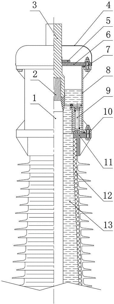
[0010] According to the accompanying drawings, the present invention is a DC cable terminal oil-gas interface lifting device, which is applied to DC cable terminals and can also be applied to UHV AC cable terminals, including cable 1, cable core 2, outlet rod 3, top cover 6, rain cover 4. Insulating bushing 12, insulating oil 13, bushing flange 11 and prefabricated oil tank 8. The prefabricated oil tank 8 has no bottom and no cover, one end of which is connected to the sleeve flange 11 by the second tightening bolt 10, and the other end is connected to the top cover 6 by the first tightening bolt 7, and is connected to the DC cable terminal through the insulating sleeve 12 Insulating oil 13 is poured into the cavity to lift the insulating oil interface upward until the interface height of the insulating oil 13 is raised to more than half of the height of the prefabricated oil tank 8, and the interface height of the insulating oil 13 exceeds the horizontal plane of the casing fl...


PUM


Abstract

The invention discloses a direct-current electric cable terminal oil-gas interface lifting device which comprises an electric cable, an electric cable wire core, a wire-out rod, a top cover, a rain cover, an insulation sleeve pipe, insulation oil and a sleeve pipe flange. The direct-current electric cable terminal oil-gas interface lifting device is characterized in that a prefabricated oil tank is further included, one end of the prefabricated oil tank is connected to the sleeve pipe flange through a screwing bolt, the other end of the prefabricated oil tank is connected with the top cover through the screwing bolt, a cavity of the insulation sleeve pipe of a direct-current electric cable terminal is filled with the insulation oil, so that the insulation oil interface is lifted until the height of the insulation oil interface is lifted to more than 1 / 2 of the height of the prefabricated oil tank, the height of the insulation oil interface exceeds the horizontal face of the sleeve pipe flange, a Faraday cage is formed on the sleeve pipe of the direct-current electric cable terminal, the direct-current electric cable terminal is protected, and the discharging phenomenon generated on the air interface of the direct-current electric cable terminal under the effect of a direct-current electric field or an extra-high-voltage alternating-current electric field is avoided.

Description

technical field [0001] The invention relates to an oil-gas interface lifting device for a cable terminal, and in particular discloses an oil-gas interface lifting device directly installed on the top of a DC cable terminal and an UHV cross-linked cable terminal, which is suitable for 66kV-1000kV DC cable terminals and AC cable terminals. Background technique [0002] The DC cable terminal is different from the AC cable terminal. The characteristics of the DC electric field are very different from the characteristics of the AC electric field. After the insulating sleeve of the AC cable terminal is filled with insulating oil, a part of the air cavity is reserved on the top of the insulating sleeve to run on the cable line. When the temperature changes, the height of the interface between the insulating oil and the air increases or decreases with the change of temperature, and there should be no air cavity on the top of the insulating sleeve of the DC cable terminal. The solutio...

Claims


Application Information

Patent Timeline
Patent Type & Authority Patents(China)
IPC IPC(8): H02G15/06
Inventor 何文明徐操潘维荣邹威武孙剑飞蒋孟男张荣瞿金山王福生邵斌韩丽娟
Owner 上海三原电缆附件有限公司
Why Eureka
Try Eureka