Load driving device and driving method thereof

A load driving and driving signal technology, which is applied in the direction of lighting devices, lamp circuit layout, light source, etc., can solve the problems of increasing printed circuit boards, reducing time and energy, increasing capacitance, etc., and achieve the effect of reducing costs

Inactive Publication Date: 2014-06-25
BEYOND INNOVATION TECH
View PDF3 Cites 1 Cited by
  • Summary
  • Abstract
  • Description
  • Claims
  • Application Information

AI Technical Summary

Problems solved by technology

However, when the LED is dimmed in full darkness, the time for the LED to be on becomes shorter, and the time and energy that can be provided to the LED drive device are relatively reduced. Therefore, during the full dark period of the LED, the control chip in the LED drive device will It will fail to work due to insufficient power supply. Generally speaking, an external large capacitor must be connected to provide power to the control chip to support the entire dark period of the LED. However, if the capacitance is insufficient, the LED drive circuit will still stop working
In addition, increasing the capacitance will not only increase the process cost but also increase the required area of ​​the printed circuit board (PCB)

Method used


Image

  • Load driving device and driving method thereof
  • Load driving device and driving method thereof
  • Load driving device and driving method thereof

Examples


Embodiment Construction

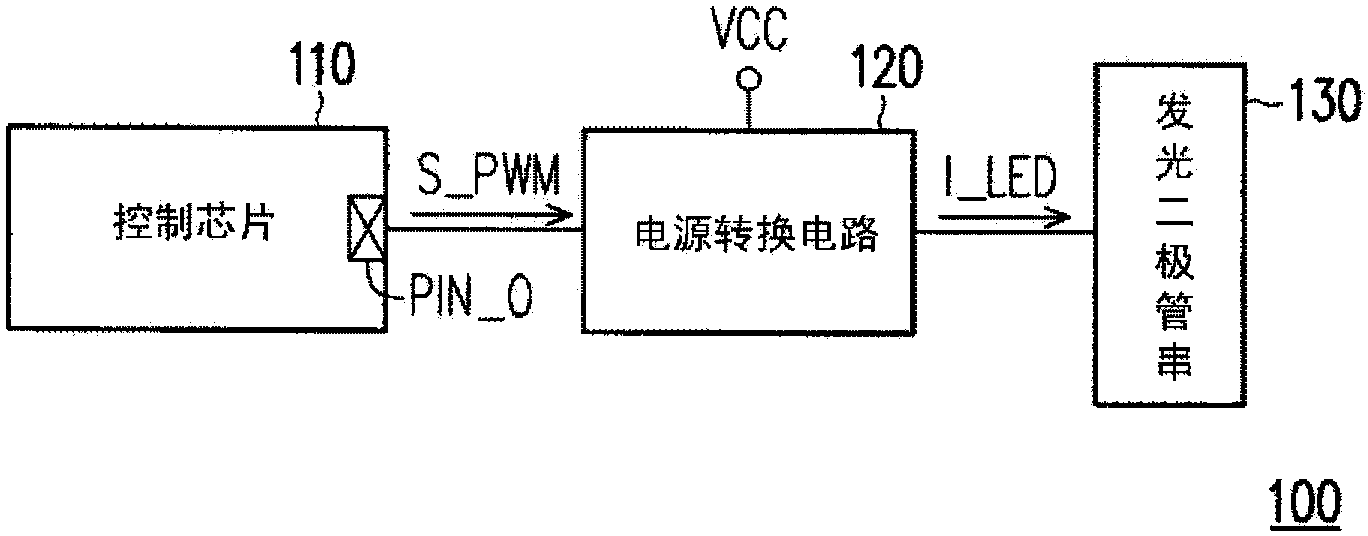
[0023] figure 1 It is a schematic block diagram of a load driving device according to an embodiment of the present invention. In this embodiment, the load driving device 100 is at least suitable for driving the LED string 130 . Please refer to figure 1 , the load driving device 100 includes a power conversion circuit 120 and a control chip 110 . The power conversion circuit 120 is coupled to the LED string 130 . The control chip 110 is coupled to the power conversion circuit 110 for controlling the operation of the power conversion circuit 120 . exist figure 1 Under the structure of the power conversion circuit 120 shown, the power conversion circuit 120 switches to enable or disable the power conversion in response to the pulse width modulation (Pulse Width Modulation, PWM) signal S_PWM provided by the output pin PIN_O of the control chip 110. The circuit 120 is used for the DC input voltage VCC to drive the LED string 130 .

[0024] In order to further describe the emb...


PUM


Abstract

The invention relates to a load driving device and a driving method thereof. The load driving device receives direct current input voltage, and reflects gate pulse width modulation signals to provide direct current output voltage to a light emitting diode load. A control chip in the load driving device is configured to provide a gate pulse width modulation signal with a first default duty cycle during bright operation of dimming operation to enable the light emitting diode load to respond to the direct current output voltage and fully open, and provide a gate pulse width modulation signal with a second default duty cycle during dark operation of dimming operation to enable the light emitting diode load to respond to the direct current output voltage and weakly open. The second default duty cycle is smaller than the first default duty cycle. The current of the light emitting diode load during bright operation is greater than the current of the light emitting diode load during dark operation.

Description

technical field [0001] The present invention relates to a load driving device, and in particular to a light emitting diode driving device and a driving method thereof. Background technique [0002] A conventional light emitting diode (Light-emitting diodes, LED) driving device is generally composed of a control chip, a power switch, an external circuit and the like. Wherein, the control chip can provide a driving signal to switch the power switch, so that the LED can emit light according to the current generated by switching the power switch. With the existing LED dimming (dimming) technology, in order to achieve high contrast, the general driving device adopts pulse width modulation (Pulse Width Modulation, PWM) dimming technology, the dimming principle is to adjust the PWM dimming signal The duty cycle (Dutycycle) length, control the time ratio of LED full bright and full dark, in order to achieve the purpose of dimming. [0003] Generally, in the application of LED ligh...

Claims


Application Information

Patent Timeline
Patent Type & Authority Applications(China)
IPC IPC(8): H05B37/02
CPCY02B20/40
Inventor 林久渊黄南川高振隆
Owner BEYOND INNOVATION TECH
Why Eureka
Try Eureka