Method for producing a magnetic separation for a solenoid valve

A technology of magnetic valve and injection method, applied in the field of magnetic valve manufacturing, can solve problems such as limiting and limiting the efficiency of magnetic valve, and achieve the effects of avoiding thermal stretching, high tensile strength, and reliable sealing

Inactive Publication Date: 2014-06-25
ROBERT BOSCH GMBH
View PDF9 Cites 2 Cited by
  • Summary
  • Abstract
  • Description
  • Claims
  • Application Information

AI Technical Summary

Problems solved by technology

This limits the effect of the magnetic separation and thus significantly limits the efficiency of the magnetic valve

Method used


Image

  • Method for producing a magnetic separation for a solenoid valve
  • Method for producing a magnetic separation for a solenoid valve
  • Method for producing a magnetic separation for a solenoid valve

Examples


Embodiment Construction

[0019] Identical components are always provided with the same reference numerals in different figures and are therefore usually only referred to or referred to only once in each case.

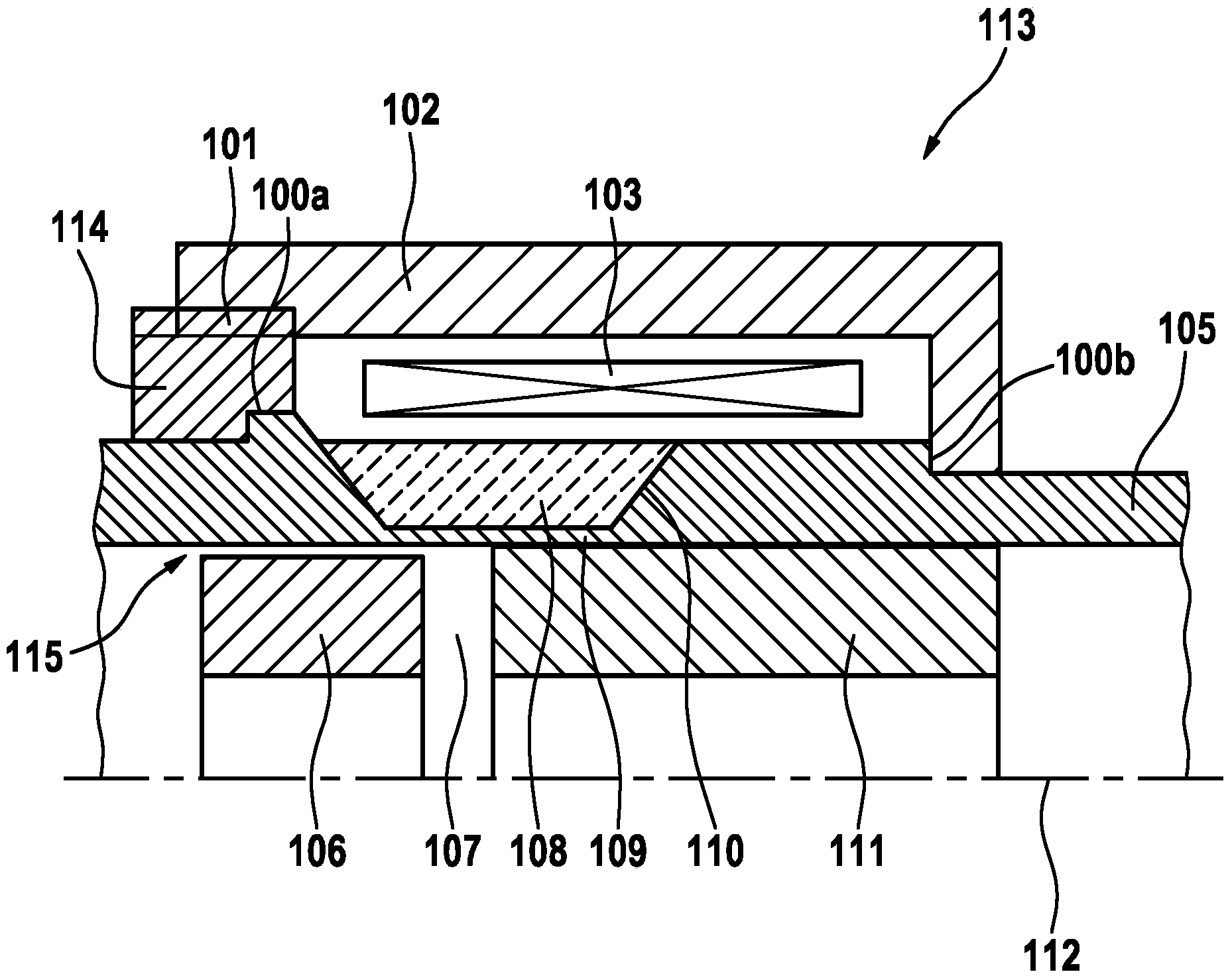
[0020] figure 1 A part of the solenoid valve 113 according to the first embodiment is shown schematically. Solenoid valve 113 is in particular an injection valve for fluid fuel (valve needle and return spring not shown). The solenoid valve is designed rotationally symmetrically about the axis 122 . An armature 106 (hereinafter also referred to as armature 106 ), which is soft-magnetic, that is to say made of ferromagnetic material, is mounted so that it can move axially and when coil 103 (hereinafter also referred to as electromagnetic coil 103 ) is switched on by Magnetic attraction caused by the soft magnetic inner pole 111 (hereinafter also referred to as the magnetic core 111 ). For high magnetic forces it is possible to ensure that the magnetic flow penetrates the armature air gap 107 a...


PUM

PropertyMeasurementUnit
melting pointaaaaaaaaaa
thicknessaaaaaaaaaa

Abstract

The invention relates to a method for producing a solenoid valve, in particular a fuel injection valve, wherein the solenoid valve has a sleeve, a valve needle, which is arranged inside the sleeve in a radial direction and guided in a displaceable manner, a magnetic coil, which is arranged outside the sleeve in a radial direction, a magnetic core, which is arranged inside the sleeve in a radial direction, and a magnetic armature, which is arranged inside the sleeve in a radial direction, axially opposite the magnetic core, wherein the magnetic armature is arranged on the valve needle, wherein the sleeve has a smaller wall thickness in a thin-walled region arranged between the magnetic armature and the magnetic coil, wherein the thin-walled region is reinforced by means of a reinforcement element to absorb radial forces, wherein the method has a method step in which the reinforcement element is applied to the sleeve in the radial direction outside the sleeve in the thin-walled region by means of a melt bath spraying method or by means of a cold gas spraying method during the method step.

Description

technical field [0001] The invention relates to a method for producing a solenoid valve according to the preamble of claim 1 . Background technique [0002] In the case of solenoid-actuated magnetic actuators for actuating solenoid valves, in particular injection valves, it is often advantageous if the solenoid coil for generating the magnetic field is arranged outside the region through which fluid, in particular fuel, flows. This simplifies assembly and prevents damage to the varnish of the coil wires, for example due to the action of fuel. To achieve such a dry coil arrangement, a metal sleeve is used which seals the fuel-filled valve interior towards the coil. In order to withstand the fuel pressure in the interior of the sleeve (eg internal pressure above 200 bar), the sleeve must have a sufficient wall thickness. At the same time it is ensured that the magnetic current can reach the magnetic circuit components (armature or armature and inner pole or magnetic core) ar...

Claims


Application Information

Patent Timeline
Patent Type & Authority Applications(China)
IPC IPC(8): H01F7/08H01F41/02
CPCH01F2007/085F02M2200/80H01F7/081F02M2200/9069F02M2200/08F02M2200/9038H01F41/0246Y10T29/4902F16K31/0675H01F41/00
Inventor J·格拉纳M·迈尔N·豪特曼R·狄克曼
Owner ROBERT BOSCH GMBH
Why Eureka
Try Eureka