Sputtering systems for liquid target materials

A sputtering system and liquid target technology, applied in sputtering coating, semiconductor devices, metal material coating technology, etc., can solve the problems of no production environment, difficult and expensive alloy targets, etc.

Inactive Publication Date: 2014-06-25
NUVOSUN
View PDF7 Cites 2 Cited by
  • Summary
  • Abstract
  • Description
  • Claims
  • Application Information

AI Technical Summary

Problems solved by technology

Such measures are generally considered too inconvenient and too expensive to be used in production environments
If indium and gallium combine to form a

Method used


Image

  • Sputtering systems for liquid target materials
  • Sputtering systems for liquid target materials
  • Sputtering systems for liquid target materials

Examples


Embodiment

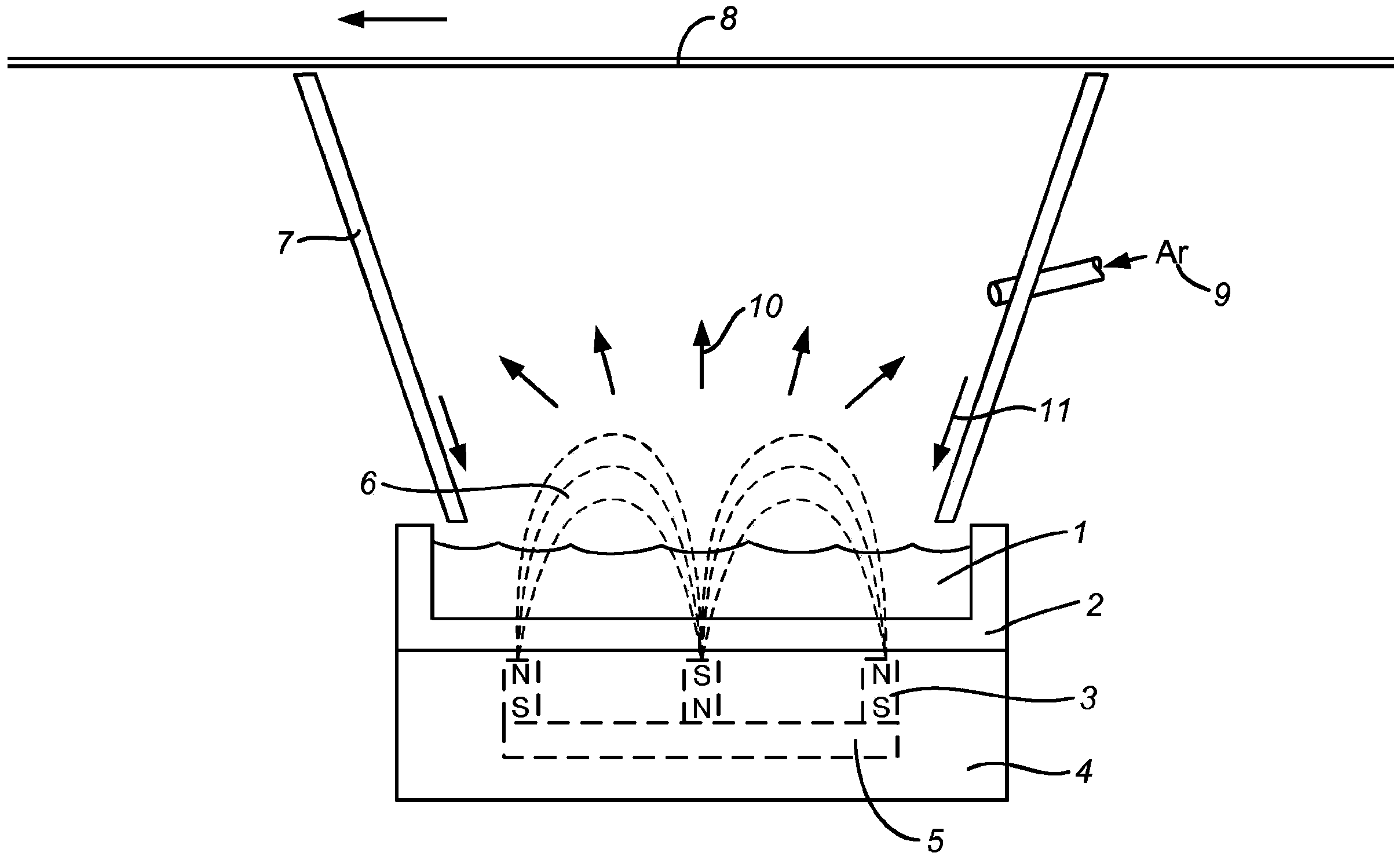
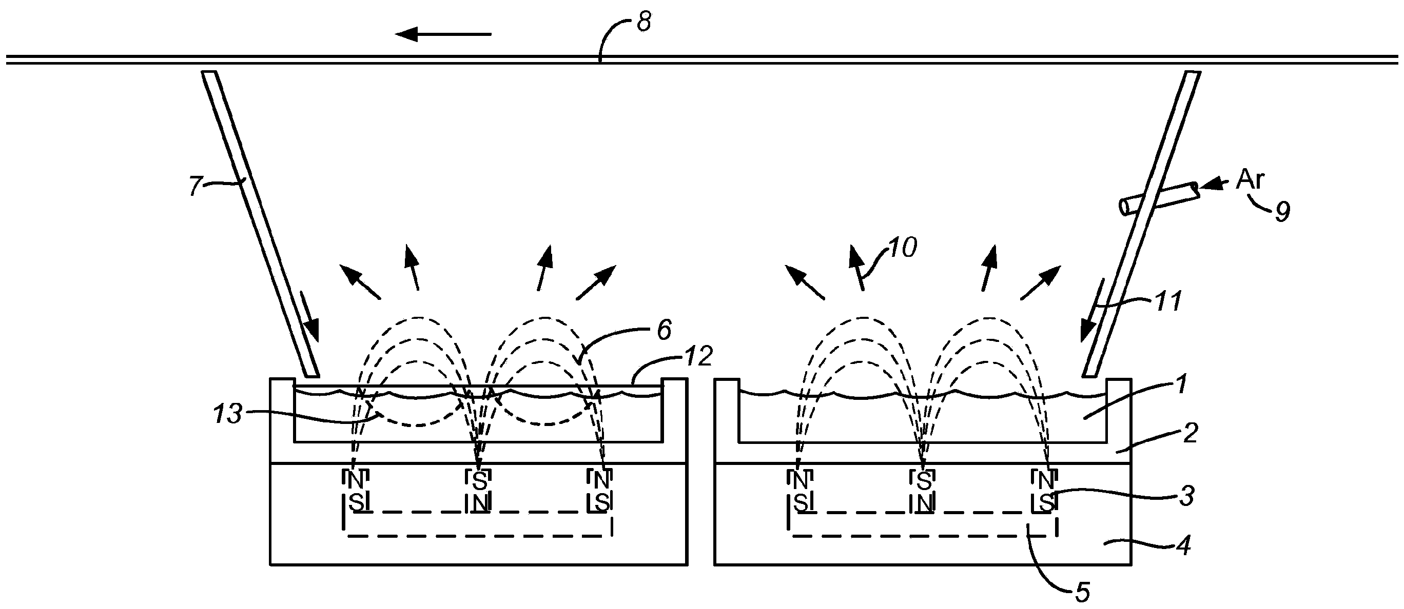
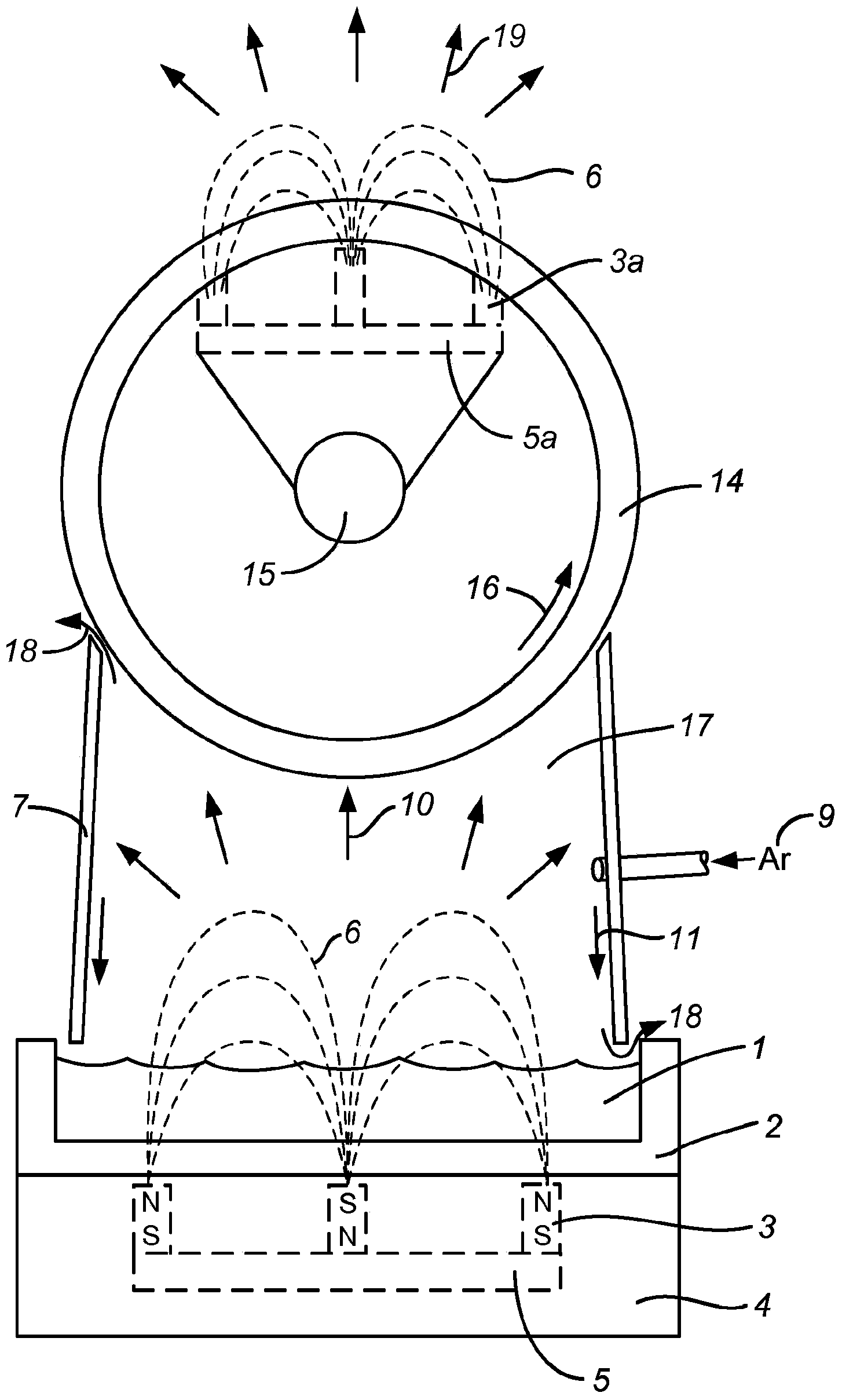
[0053] Magnetron components (such as figure 2 or image 3 shown) contains a horizontal magnetron with a gallium-containing liquid target and a rotatable magnetron with an indium-containing solid target. The flow of gallium and indium from the rotatable magnetron by applying DC power to the rotatable magnetron and horizontal magnetron while the rotatable magnetron is rotating at a rate of about 15 rpm And produced. A DC power of about 1 kW / ft target was applied to the horizontal magnetron; a DC power of about 3 kW / ft target was applied to the rotatable magnetron. chamber between the magnetrons (e.g. image 3 Chamber 17) operates at an argon pressure of about 5 millitorr (mTorr), the chamber with the magnetron assembly (e.g. image 3 The chamber 22) is operated at an argon pressure of about 3 mTorr.


PUM


Abstract

A sputtering system comprises a magnetron assembly for depositing liquid metal films on a substrate. The magnetron assembly comprises a horizontal planar magnetron with a liquid metal target, a cylindrical rotatable magnetron with a metal target and a set of one or more shields forming a chamber between the planar and the rotatable magnetron.

Description

[0001] cross reference [0002] This application claims priority to US Provisional Patent Application Serial No. 61 / 522,621, filed August 11, 2011, which is hereby incorporated by reference in its entirety. Background technique [0003] Thin-film solar cells formed with copper indium gallium (di)selenide (CIGS) as the absorber layer have become a popular solution in at least some cost-competitive solar devices. One of the more economically attractive methods of fabricating these cells utilizes wide web sputtering of the constituent materials, or alloys of those materials, onto thin flexible substrates. It has been shown that the highest laboratory cell efficiencies occur when the first part of the absorber layer consists of an indium / gallium selenide layer. This occurs in the first stage of CIGS's well-known "3-phase" method, which was developed by the National Renewable Energy Laboratory (NREL) in 1994 and described on August 15, 1995 Authorized U.S. Patent No. 5,441,897 (...

Claims


Application Information

Patent Timeline
IPC IPC(8): H01L31/18H01L31/042C23C14/34
CPCC23C14/3428C23C14/352H01J37/32036H01J37/3405H01J37/3408H01J37/3426H01J37/3429Y02E10/541C23C14/35H01L31/1844
Inventor D·R·霍拉斯
Owner NUVOSUN
Why Eureka
Try Eureka