Magnetic nano temperature imaging method and magnetic nano temperature imaging system

一种成像方法、磁纳米的技术,应用在基于磁纳米粒子顺磁特性的一维在体温度成像,磁纳米温度成像领域,能够解决不能得到组织深处温度场分布图、温度测量精度磁纳米粒子浓度分布影响等问题

Active Publication Date: 2014-07-02
HUAZHONG UNIV OF SCI & TECH
View PDF6 Cites 25 Cited by
  • Summary
  • Abstract
  • Description
  • Claims
  • Application Information

AI Technical Summary

Problems solved by technology

[0004] In addition, the current non-invasive in vivo temperature measurement method based on magnetic nanoparticles can only realize the measurement of point temperature, but cannot obtain the temperature field distribution map deep in the tissue, and the temperature measurement accuracy is affected by the concentration of magnetic nanoparticles in the deep tissue. Distribution influence

Method used


Image

  • Magnetic nano temperature imaging method and magnetic nano temperature imaging system
  • Magnetic nano temperature imaging method and magnetic nano temperature imaging system
  • Magnetic nano temperature imaging method and magnetic nano temperature imaging system

Examples


example 1

[0098] 1. Simulation model and test description:

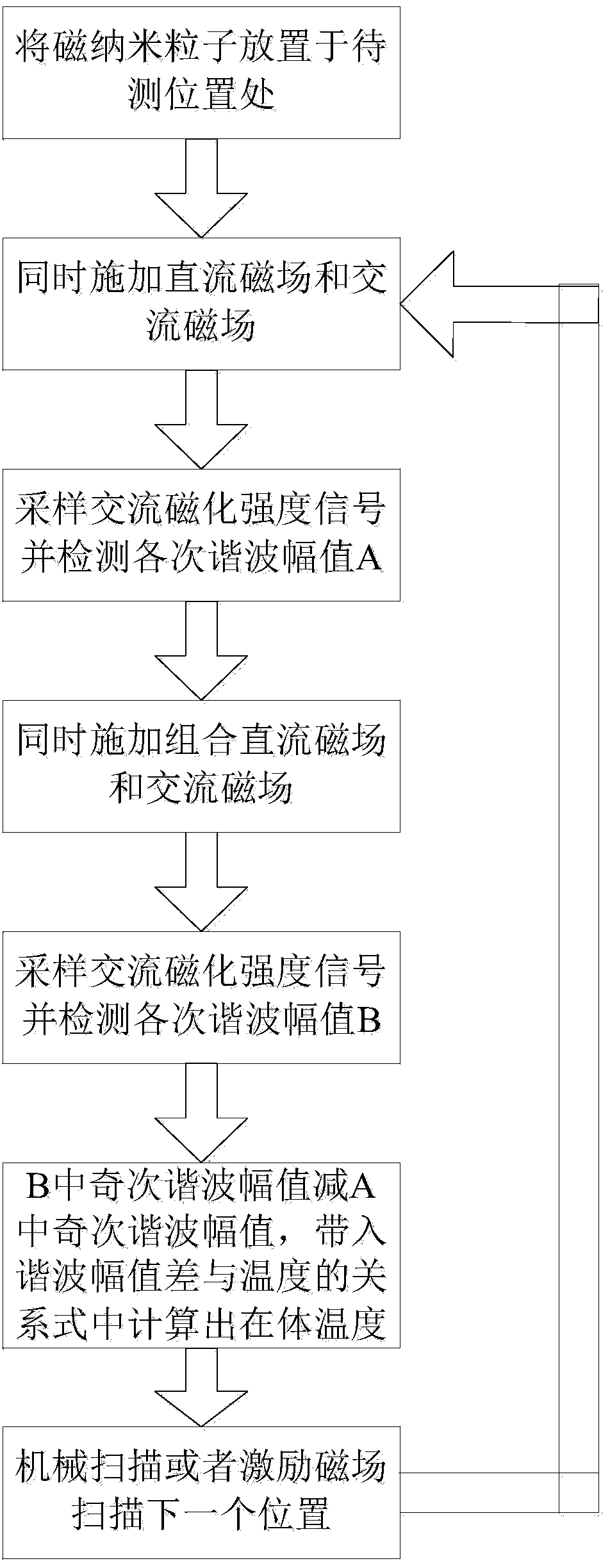
[0099] In order to study the validity and feasibility of the magnetic nano temperature imaging method, this simulation example will use the simulation data containing noise to test the method. The effective magnetic moment M of reagent particles used in the simulation test s Measured at 8.5 x 10 -19 (Supplementary note that the measured value of the effective magnetic moment is determined by the reagent type parameter), the width of the DC gradient magnetic field Δx=5mm, and the method of simulating mechanical movement moves 1mm at a time. Considering the truncation error of the approximate model obtained by using the first eight terms of the Taylor series expansion of the Langevin function, this simulation example uses the AC magnetic field amplitude H 0 =50Oe, the frequency is 160Hz, the DC magnetic field strength is 30Oe, and the awgn function in MATLAB is used to add noise to the AC magnetization signal. For different t...

example 2

[0108] 1. Simulation model and test description:

[0109] In order to study the effectiveness of the magnetic nano-temperature imaging method when the DC gradient magnetic field is nonlinear, the effective magnetic moment M of the reagent particles used in the simulation test process s Measured at 8.5 x 10 -19 (Supplementary note that the measured value of the effective magnetic moment is determined by the reagent type parameter), the imaging range is 40mm, the width of the DC gradient magnetic field Δx=20mm, and the simulated mechanical movement moves 1mm at a time. This simulation example adopts a nonlinear DC gradient magnetic field, and the amplitude of the AC magnetic field H 0 =60Oe, the frequency is 1.6kHz, the DC magnetic field strength is 30Oe, and the awgn function in MATLAB is used to add noise to the AC magnetization signal. When the concentration of magnetic nanoparticles is evenly distributed, noise with a signal-to-noise ratio of 90dB and 80dB is added to the ...


PUM


Abstract

The invention discloses a magnetic nano temperature imaging method. The method includes applying a constant direct-current magnetic field and a constant alternating-current magnetic field to an area where magnetic nanoparticle samples are positioned at the same time, collecting alternating-current magnetized strength signals of magnetic nanoparticles, and detecting out each odd harmonic amplitude value; replacing a constant direct-current gradient field by a combined direct-current magnetic field containing a gradient magnetic field, collecting alternating-current magnetized strength signals of the magnetic nanoparticles, and detecting out each odd harmonic amplitude value; calculating difference of the harmonic amplitude values of the two times; utilizing Taylor series of a Langevin function to unfold and establish a relation formula of the odd harmonic amplitude values and temperature, and solving the relation formula to acquire in-vivo temperature; changing the direct-current gradient field to a next position until temperature measuring of the whole one-dimensional space is completed. Different exciting magnetic fields are applied to the magnetic nanoparticles, so that temperature imaging of the one-dimensional space is converted into solving of point temperature of each minizone, and a temperature field of the one-dimensional space can be precisely and quickly acquired without knowing concentration of the magnetic nanoparticles.

Description

technical field [0001] The invention relates to the technical field of nanometer testing, in particular to a magnetic nanometer temperature imaging method, more specifically, a one-dimensional in vivo temperature imaging method based on the paramagnetic properties of magnetic nanoparticles. Background technique [0002] In vivo temperature imaging refers to temperature imaging of tissues performed in an intact and living individual. In the field of biomedicine such as tumor hyperthermia, it is difficult to obtain accurate information on the temperature field distribution inside the living body, resulting in the ineffective use of many medical methods. At present, in-body temperature measurement methods are divided into invasive measurement and non-invasive measurement. The invasive temperature measurement method is simple, which is convenient for direct real-time and high-precision monitoring of the lesion temperature. However, it is more invasive, and the insertion of nee...

Claims


Application Information

Patent Timeline
Patent Type & Authority Applications(China)
IPC IPC(8): A61B5/01
CPCA61B5/01A61B5/0515G01K7/36G01R33/1276A61B5/7278
Inventor 刘文中皮仕强毛文平钟景何乐
Owner HUAZHONG UNIV OF SCI & TECH
Why Eureka
Try Eureka