Clutching brake

A technology of brakes and clutches, which is applied to brake actuators, rotary printing machines, printing, etc., can solve the problems of machine equipment wear and parking inconvenience, and achieve the effects of small wear, reliable parking effect, and no safety hazards

Inactive Publication Date: 2014-07-02
赵东顺
View PDF6 Cites 1 Cited by
  • Summary
  • Abstract
  • Description
  • Claims
  • Application Information

AI Technical Summary

Problems solved by technology

[0004] The purpose of the present invention is to overcome the shortcomings of the above-mentioned prior art, provide a clutch brake that can achieve a reliable parking effect, and solve the problems of inconvenient parking of high-speed printing machines in the prior art and easy to cause serious wear and tear on the machine equipment

Method used


Image

  • Clutching brake

Examples


Embodiment

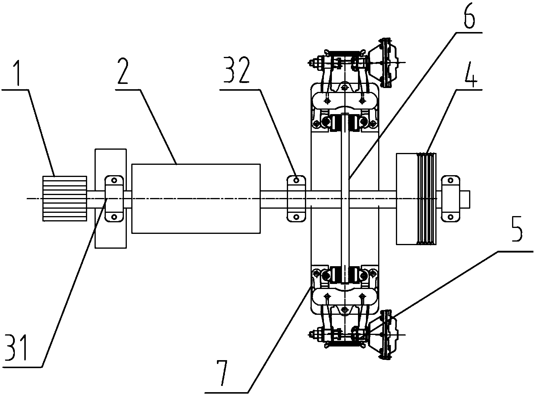
[0015] Such as figure 1 As shown, the clutch brake includes a printing press main body 1 and a driving shaft 2 connected to the printing press main body 1 through a first coupling 31. The driving shaft 2 is connected with a driven shaft 4, and the driven shaft 4 A pulley that can be connected to the belt is provided, and the driven shaft 4 is connected to the driving shaft 2 through the second coupling 32, and an annular mounting base 7 is installed between the second coupling 32 and the driven wheel 4. An annular brake wheel 6 is disposed on the seat 7, and a pneumatic actuator 5 is also connected to the installation base 7, and the pneumatic actuator 5 controls the engagement and release of the brake wheel 6.

[0016] Preferably, the annular brake wheel 6 is meshed with the driven wheel 4 through gears.

[0017] When the present invention works, the remote microcomputer is connected with the pneumatic actuator 5 in advance, and the brake air pressure and the release air pre...


PUM


Abstract

The invention discloses a clutching brake. The clutching brake comprises a printer body and a driving shaft connected with the printer body through a first coupling. A driven shaft is connected to the driving shaft through a second coupling and provided with a belt wheel capable of being connected with a belt. An annular installing base is installed between the second coupling and a driven wheel and provided with an annular braking wheel, and a pneumatic executor is connected to the installing base and controls meshing and releasing of the braking wheel. Because the pneumatic executor controlled by a remote microcomputer is adopted to control meshing and releasing of the annular braking wheel to achieve parking, the clutching brake has the advantages that the parking effect is reliable, potential safety hazards do not exist, and abrasion to a machine is small.

Description

technical field [0001] The invention relates to a brake device, in particular to a clutch brake applied to a high-speed screen printing machine, which belongs to the field of printing equipment. Background technique [0002] my country is an ancient country with four great inventions in history and culture. As early as the Northern Song Dynasty, Bi Sheng invented movable type printing, which ushered in a new era of printing. With the advancement of science and technology, printing technology has been continuously improved. Such high-tech printing equipment is manufactured, and high-level printing technologies such as digital printing and four-color printing are constantly being adopted. For printing, good printing technology must be supported by good printing equipment. Among them, Screen printing machines and UV light-curing printing machines have gradually become the mainstream. They have many advantages such as high printing efficiency, good effect, and low repair rate. ...

Claims


Application Information

Patent Timeline
IPC IPC(8): B41F15/14F16D65/14F16D121/02
Inventor 赵东顺
Owner 赵东顺
Why Eureka
Try Eureka