Hydraulic device for automobile braking energy recovery

A braking energy recovery and energy recovery technology, applied in the field of hydraulic devices, can solve problems such as high cost and complex structure, and achieve the effects of simplifying algorithms, improving work efficiency, and improving braking energy recovery efficiency.

Inactive Publication Date: 2014-07-02
JILIN UNIV
View PDF10 Cites 23 Cited by
  • Summary
  • Abstract
  • Description
  • Claims
  • Application Information

AI Technical Summary

Problems solved by technology

[0010] The technical problem to be solved by the present invention is to overcome the problems of complex structure, high cost and de

Method used


Image

  • Hydraulic device for automobile braking energy recovery
  • Hydraulic device for automobile braking energy recovery
  • Hydraulic device for automobile braking energy recovery

Examples


Embodiment Construction

[0032] The present invention is described in detail below in conjunction with accompanying drawing:

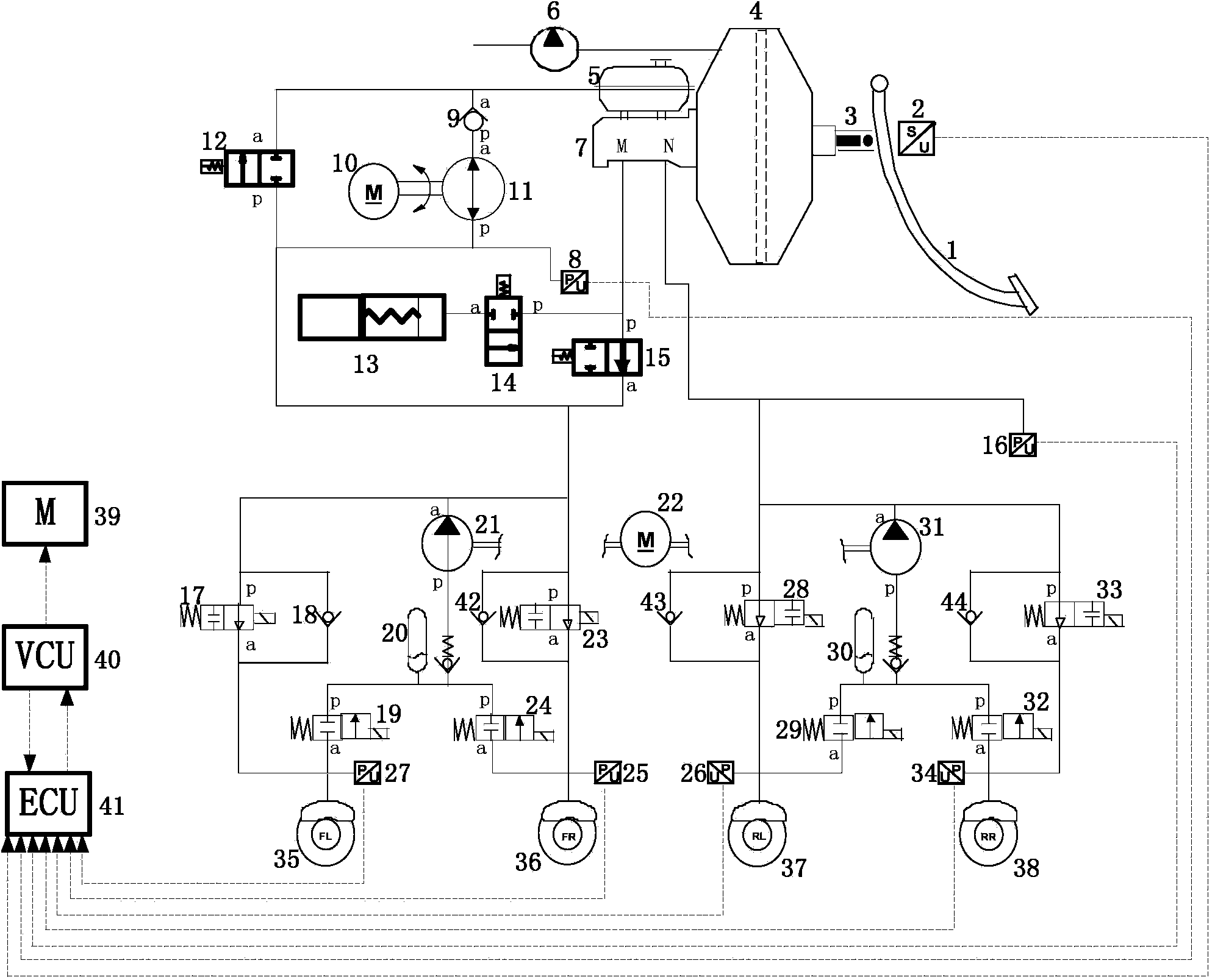
[0033] refer to figure 1 , The hydraulic device for recovering the braking energy of the vehicle according to the present invention includes a master cylinder vacuum booster assembly, a hydraulic control unit for braking energy recovery, an ABS hydraulic control unit and an electronic control device.

[0034] The master cylinder vacuum booster assembly includes a brake pedal 1 , a front end ejector rod 3 of the vacuum booster, a vacuum booster 4 , an oil pot 5 , a vacuum pump 6 and a brake master cylinder 7 . Wherein the function of the vacuum pump 6 is to simulate the negative pressure source of the engine intake pipe of the original car.

[0035] The brake pedal 1 selection pedal ratio is 3.5. Vacuum pump 6 selects a vacuum pump that can reach a vacuum degree of 40-67kPa. The diameter of the brake master cylinder is 23.6mm.

[0036] The top of the brake pedal 1 is fixed ...


PUM


Abstract

The invention discloses a hydraulic device for automobile braking energy recovery. The hydraulic device aims at solving the problems that in the prior art, the structure is complex, cost is high, and the foreign technology is depended. The hydraulic device for automobile braking energy recovery comprises a main cylinder vacuum booster assembly, a braking energy recovery hydraulic control unit, an ABS hydraulic control unit and an electronic control device. The main cylinder vacuum booster assembly comprises a braking pedal, an oil pot (5) and a braking main cylinder. An opening N of the braking main cylinder is connected with a pipe of an opening p of a left back wheel oil inlet electromagnetic valve of the ABS hydraulic control unit, an opening p of a normally-open electromagnetic valve of the braking energy recovery hydraulic control unit is connected with an opening M of the braking main cylinder through a pipe, an opening a of the normally-open electromagnetic valve and an opening p of a normally-closed linear electromagnetic valve are connected with an opening p of a right front liquid inlet electromagnetic valve of the ABS hydraulic control unit through a pipe, an opening a of the normally-closed linear electromagnetic valve is connected with the oil pot (5) through a pipe, and the electronic control device and the braking energy recovery hydraulic control unit are connected with the ABS hydraulic control unit through pipes.

Description

technical field [0001] The invention relates to a hydraulic device in the field of automobile braking systems, more precisely, the invention relates to a hydraulic device applied to the recovery of braking energy of automobiles. Background technique [0002] When the new energy vehicle decelerates or brakes, the motor can convert part of the mechanical energy of the car into electrical energy and store it in the battery, and at the same time generate part of the braking force to realize the deceleration or braking of the car. When the car accelerates again, the motor will store it The energy stored in the battery is converted into kinetic energy for driving the car again. Therefore, the recovery of braking energy is an effective way for hybrid and pure electric vehicles to save fuel and reduce emissions. A hydraulic system and control method for efficient braking energy recovery suitable for new energy vehicles is very urgent. [0003] The research on the braking energy rec...

Claims


Application Information

Patent Timeline
IPC IPC(8): B60T13/565B60T13/52B60T13/72B60L7/10
Inventor 初亮马文涛杨毅王彦波蔡建伟赵迪张世桐黄禹霆张永生姚亮
Owner JILIN UNIV
Why Eureka
Try Eureka