Core mold for concrete filling

A core mold and sealing mold technology, which is applied in the fields of mold shells/templates/work frames, on-site preparation of building components, construction, etc., can solve the problems of large space occupation, inconvenient storage and transportation, and uneven cast-in-place concrete structure.

Inactive Publication Date: 2014-07-02
湖南邱则有专利战略策划有限公司
View PDF7 Cites 3 Cited by
  • Summary
  • Abstract
  • Description
  • Claims
  • Application Information

AI Technical Summary

Problems solved by technology

The production of this kind of component is simple, but there are many consumables and the storage and transportation are extremely inconvenient due to the large space occupied by the component itself. At the same time, because the structure of the component itself is a rigid wall supporting the construction load, its compression and impact resistance The ability is weak, and it is easy to be damaged during the construction process, especially during the vibration compaction process, causing the cast-in-place concrete to enter the component, resulting in the uneven structure of the cast-in-place concrete
In order to solve the above problems, the applicant has studied another type of component, which uses air in the component, such as a component formed by blow molding. For example, the application number applied by the applicant on May 10, 2004 is 200410038947.8, publication number CN1696455, titled "A Cavity Component" inventio

Method used


Image

  • Core mold for concrete filling
  • Core mold for concrete filling
  • Core mold for concrete filling

Examples


Embodiment Construction

[0057] The present invention will be further described below in conjunction with drawings and embodiments.

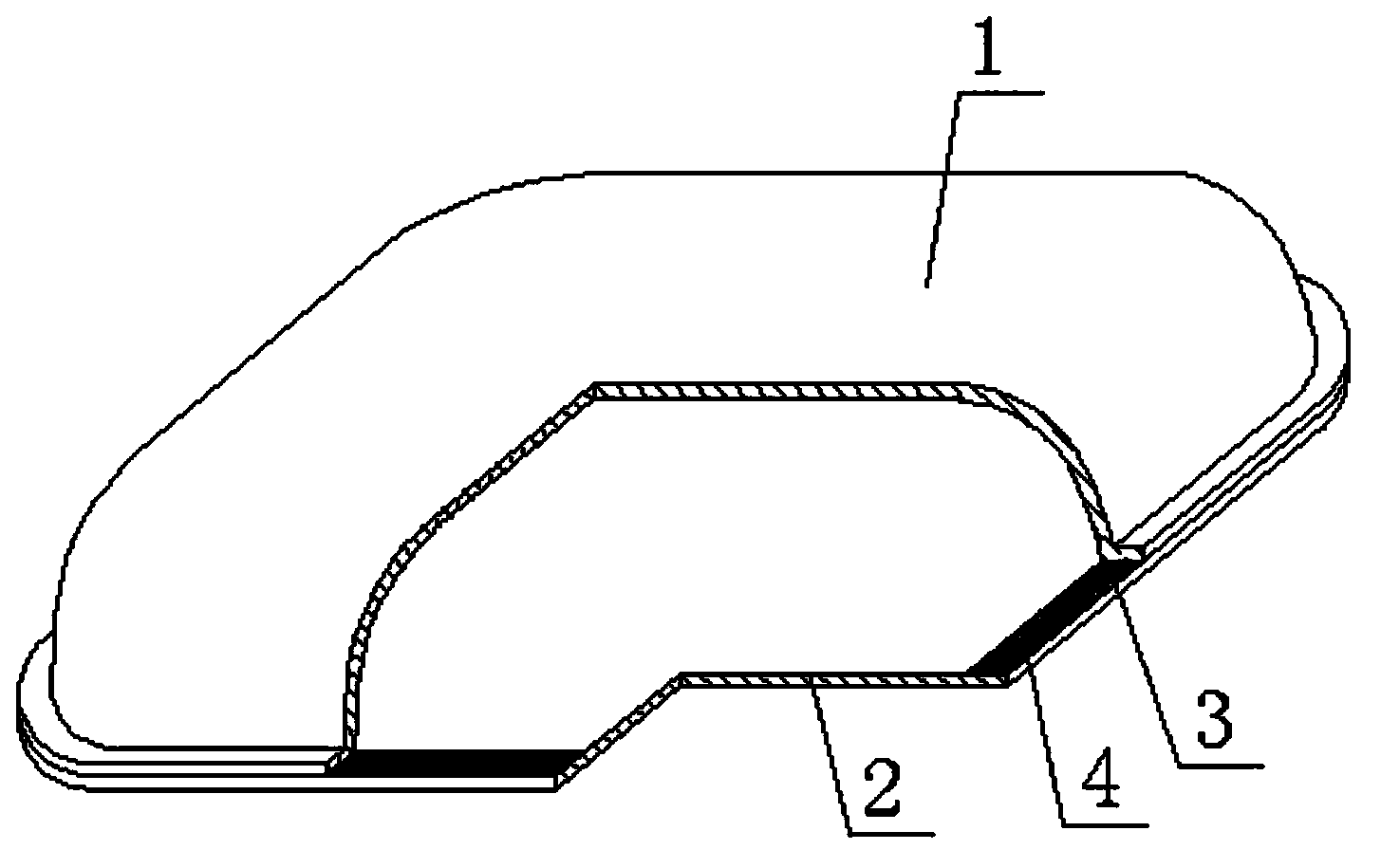
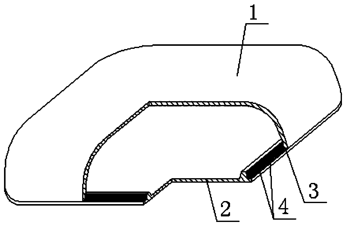
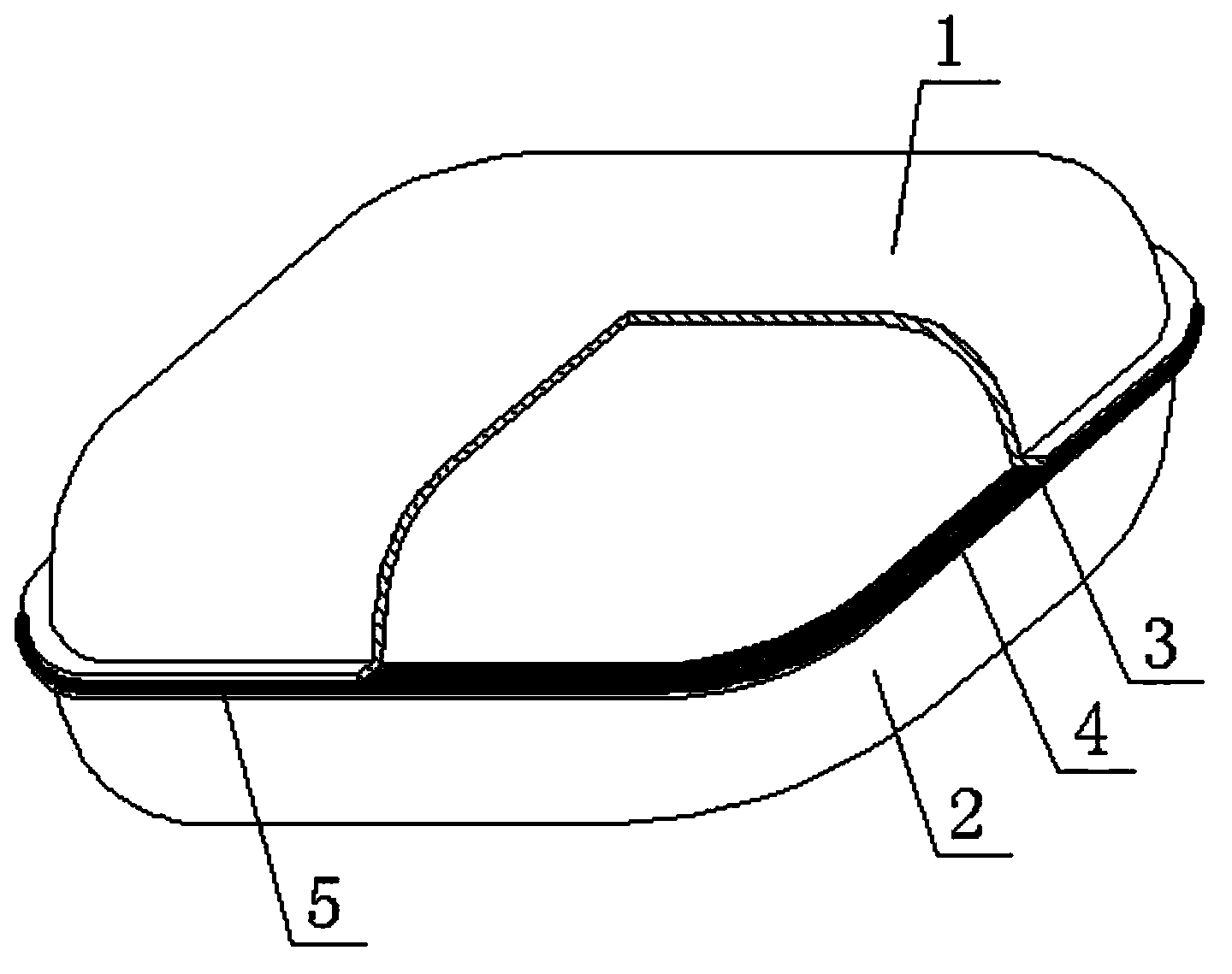
[0058] As shown in the accompanying drawings, the present invention comprises a basin-shaped mold 1 and a sealing mold 2, the basin-shaped mold 1 and the sealing mold 2 are relatively fastened to form a cavity, and the feature is that the basin-shaped mold 1 and the sealing mold 2 are folded together, After the plastics of the two joining parts 4 of the basin mouth part 3 and the sealing die 2 are heated and melted simultaneously, the melted parts are joined and welded into one body. figure 1 It is a structural schematic diagram of Embodiment 1 of the present invention. In each accompanying drawing, 1 is a pot-shaped mold, 2 is a sealing mold, 3 is a basin mouth position, and 4 is a joining position. In each accompanying drawing, those with the same numbering have the same description. Such as figure 1 As shown, the basin-shaped mold 1 and the sealing mold 2 are relat...


PUM


Abstract

A core mold for concrete filling comprises a basin-shaped mold (1) and a sealing mold (2). The basin-shaped mold (1) and the sealing mold (2) are in butt joint to form a cavity. The core mold is characterized in that the basin-shaped mold (1) and the sealing mold (2) are in butt joint; melted portions are jointly welded into a whole after plastic at two joint portions (4), where a basin mouth portion (3) is in butt joint with the sealing mold (2), is heated and melted. Before butt joint of the basin-shaped mold and the sealing mold, the melted portions are jointly melted into a whole after the plastic of the joint portions, where the basin mouth portion is in butt joint with the sealing mold, is heated and melted simultaneously, jointing quality can be guaranteed during spicing by a hot-melting joint belt, and jointing interfaces of the two components can be increased, so that the two components can be really connected to be integrated; through the hot-melting joint mode, jointing speed, efficiency and connection strength are high; the core mold is applicable to hollow floors, roofs, walls, foundation slabs and bridges with cast-in-place reinforced concrete or prestressed reinforced concrete, and particularly applicable to the hollow floors.

Description

(1) Technical field [0001] The invention relates to a core mold for concrete filling. (2) Background technology [0002] At present, in the existing technology, the hole-forming components of cast-in-place hollow slabs are permanent mandrels, such as paper tubes, plastic tubes, metal bellows, and lightweight materials for mandrels. Small floor weight. Among them, it is divided into two types, one is to support the strength of the component itself to form holes, such as the patent No. ZL99249798.1 applied by the applicant on November 29, 1999, and the name is "fiber reinforced thin film for reinforced concrete filling". Wall member” utility model patent, which discloses a thin-walled formwork member, including an upper plate, surrounding side walls, and lower bottom. The upper plate, surrounding side walls, and lower bottom form a polyhedral cavity. The upper plate, surrounding side walls, and lower The sole contains fiber reinforcements. The production of this kind of com...

Claims


Application Information

Patent Timeline
IPC IPC(8): E04G15/06
Inventor 邱则有
Owner 湖南邱则有专利战略策划有限公司
Why Eureka
Try Eureka