

Discharging butterfly valve
A butterfly valve and valve seat technology, applied in the field of powder medicine discharge valve, can solve the problems of easy opening, unfavorable cleaning, complex structure, etc., and achieve the effect of small braking resistance, simple structure, and meeting cleaning requirements.
- Summary
- Abstract
- Description
- Claims
- Application Information
AI Technical Summary
Problems solved by technology
Method used
Image

Examples
Embodiment 1
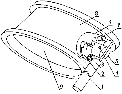
[0019] Such as figure 1 , a discharge butterfly valve provided by the present invention includes a valve seat 8, a valve core 9 located in the inner cavity of the valve seat 8, and a valve stem 5 fixedly connected to the valve core 9 at one end, and the free end of the valve stem 5 is positioned at the valve The outside of seat 8 also includes rod-shaped handle 1, spring 3 and slot seat 7, the end of the free end of valve stem 5 is provided with a bar-shaped groove, handle 1 is partly located in the bar-shaped groove, and handle 1 and valve stem 5 Through the hinged connection of the hinge nail 4 crossing the strip groove, the slot seat 7 is fixedly connected to the valve seat 8, the slot seat 7 is provided with a plurality of slots 6, and the handle 1 part is located in any slot 6, so One end of the spring 3 is in contact with the handle 1 and is compressed between the valve seat 8 and the handle 1 , and the hinge nail 4 is located between the spring 3 and the slot 6 .
[00...
Embodiment 2
[0022] This embodiment is further limited on the basis of embodiment 1: as figure 1 , also includes a follower block 2 fixed on the valve stem 5, and the side of the free end of the card slot seat 7 is also provided with an arc whose arc length is within the range of one-third to one-half of the circumference of the card slot seat 7 The gaps and slots 6 are evenly distributed in the area other than the arc-shaped gaps on the free end, and the follower block 2 is located in the arc-shaped gaps. The above setting is convenient to set the card slot 6 along the circumferential direction of the card slot seat 7 at the end of the card slot seat 7. When the number of the card slots 6 is equal, the card slot seat 7 of the above structural form is compared with other structural forms. It has the characteristics of small size.
Embodiment 3
[0024] The present embodiment is further limited on the basis of embodiment 2: as figure 1 , also includes a follower block 2 fixed on the valve stem 5, and the side of the free end of the card slot seat 7 is also provided with an arc whose arc length is within the range of one-third to one-half of the circumference of the card slot seat 7 The gaps and slots 6 are evenly distributed in the area other than the arc-shaped gaps on the free end, and the follower block 2 is located in the arc-shaped gaps.
[0025] In order to make the spring 3 rotate with the same angular velocity of the valve stem 5 and avoid excessive twisting of the spring 3 when adjusting the opening of the butterfly valve, the two ends of the spring 3 are in contact with the follower block 2 and the handle 1 respectively.
[0026] The follower block 2 is also provided with a blind hole, and the spring 3 is partly located in the blind hole.
[0027] The set follower block 2 is used to limit the rotation angle ...
PUM
 Abstract
Description
Claims
Application Information