Intelligent-control efficient kiln waste heat utilization system

A kiln and waste heat technology, applied in heating systems, hot water central heating systems, furnace control devices, etc., to avoid low-temperature corrosion and enhance heat transfer

Inactive Publication Date: 2014-07-02
SHANDONG UNIV OF TECH
View PDF4 Cites 11 Cited by
  • Summary
  • Abstract
  • Description
  • Claims
  • Application Information

AI Technical Summary

Problems solved by technology

However, how to ensure the maximum utilization and avoid low-temperature corrosion in

Method used


Image

  • Intelligent-control efficient kiln waste heat utilization system
  • Intelligent-control efficient kiln waste heat utilization system
  • Intelligent-control efficient kiln waste heat utilization system

Examples


Embodiment Construction

[0038] The specific embodiments of the present invention will be described in detail below in conjunction with the accompanying drawings.

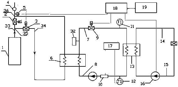
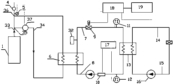
[0039] Such as Figure 1-2 As shown, a cogeneration system of heat and power includes a waste heat system, a heat exchange system and a heat dissipation system, wherein the heat exchange relationship between the waste heat system and the heat exchange system is carried out through an air-water heat exchanger 6, and the heat exchange system and the heat dissipation system are passed through A heat exchanger 13 is connected for heat exchange. figure 1 A kiln waste heat utilization system is shown, the system includes a kiln 1, a main flue 33, a bypass flue 34 and an air-water heat exchanger 6, and the flue gas generated by the kiln passes through the bypass flue inlet 35 After entering the air-water heat exchanger 6, the flue gas after heat exchange flows into the main flue 33 through the outlet 36 of the bypass flue and then is discharged....


PUM


Abstract

The invention provides an intelligent-control efficient kiln waste heat utilization system which comprises a kiln, a main flue, a bypass flue and a gas-water heat exchanger. Smoke generated by the kiln enters the gas-water heat exchanger through an inlet of the bypass flue, and the smoke after heat exchanging flows into the main flue through an outlet of the bypass flue to be discharged. A main flue adjustment valve is arranged at the position, between the inlet of the bypass flue and the outlet of the bypass flue, of the main flue and used for adjusting the amount of the smoke of the main flue; meanwhile, a bypass flue adjustment valve is arranged on the bypass flue and used for adjusting the amount of the smoke of the bypass flue. According to the intelligent-control efficient kiln waste heat utilization system, the opening degrees of the valves are adjusted, and low-temperature corrosion is avoided; meanwhile, optimization of waste heat utilization is achieved to save energy, and the environment-friendly and energy-saving aims are achieved.

Description

technical field [0001] The invention belongs to the field of waste heat utilization and belongs to the field of F27 kilns. Background technique [0002] With the rapid development of my country's economy, energy consumption is increasing day by day, and the problem of deteriorating urban air quality is becoming more and more prominent. It is urgent to save energy and reduce the emission of harmful environmental substances. In the common thermal power field, one of the main reasons for high energy consumption and serious pollution is that the exhaust gas temperature of the flue gas is too high, which wastes a lot of energy and causes environmental pollution. The cement industry is a high energy consumption and high pollution industry. The tail gas produced by cement rotary kiln has high dust concentration and poor quality. The waste heat utilization system for cement rotary kiln can recover and reuse the waste heat of tail gas to achieve the purpose of energy saving and emi...

Claims


Application Information

Patent Timeline
IPC IPC(8): F27D17/00F27D19/00F24D3/10F24D19/10
CPCY02P10/25
Inventor 李艳李梦红崔孝风孙学用孙福振荣启华
Owner SHANDONG UNIV OF TECH
Why Eureka
Try Eureka