Internal suspension core optical fiber grating temperature self-compensation microfluidic sensor and internal suspension core optical fiber

An automatic compensation and fiber grating technology, which is applied in cladding optical fiber, optical waveguide and light guide, and phase influence characteristic measurement, etc., can solve the problems of unfavorable device integration, increase sampling amount, etc., achieve simple structure, improve detection accuracy, and accurate detection results Effect

Active Publication Date: 2014-07-02
HARBIN ENG UNIV
View PDF2 Cites 6 Cited by
  • Summary
  • Abstract
  • Description
  • Claims
  • Application Information

AI Technical Summary

Problems solved by technology

Although this type of fiber Bragg grating sensor has the superior characteristics of fiber Bragg grating, it can use the resonant wavelength for concentration detection and obtain high signal-to-noise ratio. However, most fiber Bragg grating sensors are prepared by traditional optical fibers at present. The sample needs to be in contact with the fiber Bragg grating from the outside of the fiber. Sensing can only be realized by using a sample cell, which not only increases the sampling amount, but is also not conducive to device integration

Method used


Image

  • Internal suspension core optical fiber grating temperature self-compensation microfluidic sensor and internal suspension core optical fiber
  • Internal suspension core optical fiber grating temperature self-compensation microfluidic sensor and internal suspension core optical fiber
  • Internal suspension core optical fiber grating temperature self-compensation microfluidic sensor and internal suspension core optical fiber

Examples


Embodiment Construction

[0017] The following examples describe the present invention in more detail.

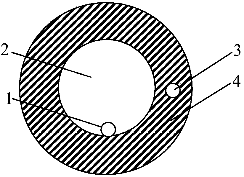
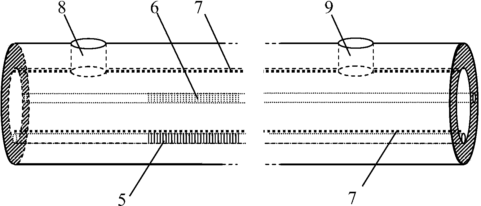
[0018] combine figure 1 , the structural feature of the inner suspension core fiber is that it has two cores, wherein the core 1 is located on the inner wall of the inner hole 2 of the fiber, and the core 3 is located inside the ring-shaped cladding 4 of the fiber, and the diameter of each core is 5 μm , the diameter of the entire fiber is 125 μm. Most of the core 1 located on the inner surface of the fiber tunnel is exposed outside the cladding, and the area exposed outside the cladding 4 is 90% of the surface area of ​​the core. combine figure 2 As shown, fiber gratings 5 ​​and 6 with the same structure are written at the same longitudinal position on the two cores, wherein the fiber grating 5 on the core 1 is used as the sensing unit, and the fiber grating 6 on the core 3 is used as the reference than unit. The sensing fiber grating 5 can be directly exposed to the micro-flow of the object t...


PUM

PropertyMeasurementUnit
diameteraaaaaaaaaa
diameteraaaaaaaaaa
diameteraaaaaaaaaa

Abstract

The invention provides an internal suspension core optical fiber grating temperature self-compensation microfluidic sensor. An internal suspension core optical fiber is provided with two fiber cores, wherein the first fiber core (1) is arranged on the inner wall of an optical fiber inner pore duct (2), and the second fiber core (3) is arranged in a ring band-shaped cladding layer (4) of the optical fiber; a fiber grating (5) and a fiber grating (6) which have the same structure are respectively written into the same longitudinal positions of the two fiber cores; the fiber grating (5) and the fiber grating (6) are respectively taken as a sensing unit and a reference unit; the optical fiber inner pore duct (2) is taken as a micro-channel of a sample sensing place; the surface of the micro-channel is provided with micropores (8 and 9); a light source (16) is connected with a standard optical fiber (11) by a coupler (17); the standard optical fiber (11) is connected with the internal suspension core optical fiber (10) by a first tapering point (13); the divided beams respectively enter the fiber core (1) and the fiber core (3), pass through the fiber grating (5) and the fiber grating (6), and finally enter a standard optical fiber (12) after being coupled; the standard optical fiber (12) is connected with a spectrograph (18). The grating temperature self-compensation microfluidic sensor can be used for the multiple fields of medicine, environment detection, food and the like, is accurate in detection result and is not influenced by the environment temperature.

Description

technical field [0001] The invention relates to a microfluidic sensing device in an optical fiber, in particular to a high-sensitivity microfluidic fiber grating on-line sensor based on an optical fiber containing an inner suspension core. Background technique [0002] Fiber Bragg gratings are widely used in the field of sensing, and can be easily embedded in optical fiber systems and sensors to form many optical fiber devices with unique properties, which greatly promotes the development of fiber Bragg grating application technology. Its reflection or transmission peak position is related to the period length of the grating and the refractive index of the fiber core. When external physical quantities such as temperature, strain, and the environment outside the fiber core change, it will affect the refractive index modulation period of the fiber grating and the refractive index of the fiber core. , thus causing the change of the reflection or transmission peak of the fiber g...

Claims


Application Information

Patent Timeline
Patent Type & Authority Applications(China)
IPC IPC(8): G01N21/41G02B6/02
Inventor 杨兴华苑婷婷李恩涛刘春兰赵恩铭苑立波
Owner HARBIN ENG UNIV
Why Eureka
Try Eureka