Modularization multi-level current converter bridge arm current direction measuring device and judgment method

A modular multi-level, current direction technology, applied in the direction of current indication, electronic circuit testing, voltage polarity indication, etc., can solve the problem of inability to accurately measure electromagnetic current transformers, reduce reliability, and improve the current direction detection device Complexity and cost issues, to achieve the effect of solving development or selection difficulties, improving reliability, and reducing complexity and cost

Active Publication Date: 2014-07-02
STATE GRID CORP OF CHINA +2
View PDF6 Cites 1 Cited by
  • Summary
  • Abstract
  • Description
  • Claims
  • Application Information

AI Technical Summary

Problems solved by technology

In addition to the fundamental wave component, the bridge arm current also contains a DC component and a frequency multiplier component, which cannot be accurately measured by an electromagnetic current transformer. The existing measurement method is to measure the bridge arm current through a current sensor, and then directly judge the current direction
Although this judgment method itself is simple and direct, the disadvantage of this measurement method is that the measurement point is on the connecting line of the bridge arm, and the insulation level of the current sensor and its isolated power supply is very high. The insulation level is the same as that of the AC side of the device, that is, it generally reaches tens to hundreds of kV levels
This makes the development or selection of high-voltage current sensors difficult, greatly increases the complexity and cost of the current direction detection device, and also reduces the reliability

Method used


Image

  • Modularization multi-level current converter bridge arm current direction measuring device and judgment method
  • Modularization multi-level current converter bridge arm current direction measuring device and judgment method
  • Modularization multi-level current converter bridge arm current direction measuring device and judgment method

Examples


Embodiment Construction

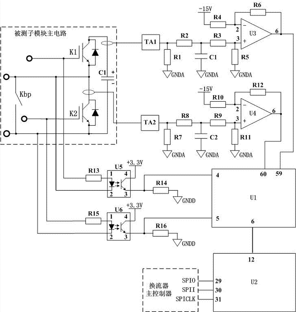
[0036] Depend on Figure 1-5 It can be seen that this embodiment includes a first single-chip microcomputer U1, a second single-chip microcomputer U2, a first current sensor TA1, a second current sensor TA2, a first operational amplifier U3, a second operational amplifier U4, a first photocoupler U5, a second photoelectric coupler Coupler U6, resistors R1-R16 and capacitors C1-C2;

[0037] The primary side of the first current sensor TA1 is set on the lead-out line of the collector of the upper switching tube K1 of the sub-module under test; the primary side of the second current sensor TA2 is set on the collector of the lower switching tube K2 of the sub-module under test lead-out line;

[0038] The resistor R2 and the resistor R3 are connected in series between the output terminal of the first current sensor TA1 and the non-inverting input terminal 3 pin of the first operational amplifier U3; the output terminal 6 pin of the first operational amplifier U3 Connect the AD si...


PUM


Abstract

The invention relates to a modularization multi-level current converter bridge arm current direction measuring device and a judgment method. The modularization multi-level current converter bridge arm current direction measuring device comprises a first single chip microcomputer U1, a second single chip microcomputer U2, a first current sensor TA1, a second current sensor TA2, a first operational amplifier U3, a second operational amplifier U4, a first photoelectric coupler U5, a second photoelectric coupler U6, resistors R1-R16, a capacitor C1 and a capacitor C2. The modularization multi-level current converter bridge arm current direction measuring device has the advantages that the bridge arm current direction is indirectly judged by detecting the current situation of an internal switching tube of a submodule according to the switching tube conduction state, and the requirement for the insulating degree of the current sensors can be greatly reduced; meanwhile, power supplies of the sensors can be isolating power supplies of a submodule drive protection circuit, and a circuit does not need to be additionally arranged; the complex degree and cost of the modularization multi-level current converter bridge arm current direction measuring device can be greatly reduced according to the characteristics, and reliability can be improved.

Description

technical field [0001] The invention belongs to the technical field of power electronics, and relates to a device for measuring the current direction of a bridge arm of a modular multilevel converter and a judging method. Background technique [0002] The continuous development of power electronics technology provides strong support for the construction of intelligent, clean and efficient modern power systems, and has been widely used in the fields of high-voltage direct current transmission (HVDC) and flexible alternating current transmission (FACTS). Modular Multilevel Converter (MMC), as a new generation of high-voltage and high-power converter device, has large power transmission capacity, active and reactive power can be independently controlled, AC output does not need complex filtering devices, high reliability, and can be It has many advantages such as power transmission to passive or weak receiving end systems, and is considered to be a representative technology...

Claims


Application Information

Patent Timeline
Patent Type & Authority Applications(China)
IPC IPC(8): G01R19/14G01R31/28
Inventor 郭捷胡文平王磊
Owner STATE GRID CORP OF CHINA
Why Eureka
Try Eureka