Feeder interconnection converter

A technology of converters and feeders, which is applied in power transmission AC networks, AC network load balancing, and AC networks to reduce harmonics/ripples, etc., and can solve problems such as low voltage, volatility, and voltage fluctuations at the end of radial feeder lines , to achieve the effect of improving power quality, balancing power distribution, and reducing burden

Active Publication Date: 2014-07-02
INST OF ELECTRICAL ENG CHINESE ACAD OF SCI
View PDF7 Cites 6 Cited by
  • Summary
  • Abstract
  • Description
  • Claims
  • Application Information

AI Technical Summary

Problems solved by technology

[0006] The purpose of the present invention is to overcome the shortcomings of traditional distributed power generation volatility, solve power quality problems such as low voltage and voltage fluctuations at the end of radial feeder lines, and propose a feeder interconnection converter

Method used


Image

  • Feeder interconnection converter
  • Feeder interconnection converter
  • Feeder interconnection converter

Examples


Embodiment 1

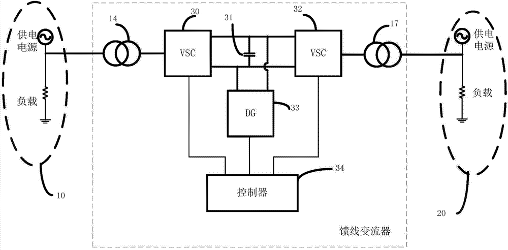
[0042] Embodiment 1 of the present invention such as figure 2As shown, the present invention includes a distributed power generation unit 33 , a first controlled power source 30 , a second controlled power source 32 , a first feeder unit 10 and a second feeder unit 20 . The distributed power generation unit 33 may be various energy power generation systems such as photovoltaic power generation, wind power generation or fuel cell power generation. The first feeder unit 10 includes a power supply and a load, and the load may be a common load or a sensitive load. The second feeder unit 20 includes a power supply and a load, and the load may be a common load or a sensitive load. The power supply of the first feeder unit 10, the load of the first feeder unit 10 and the isolation transformer 14 output by the first controlled power supply 30 are connected; the power supply of the second feeder unit 20, the load of the second feeder unit 20 and the second received The isolation tra...

Embodiment 2

[0050] Figure 7 Shown is a schematic structural diagram of the main circuit of Embodiment 2 of the feeder interconnection converter. Contains an energy storage unit 33, a first controlled power supply 30, a second controlled power supply 32, a first feeder unit 10 and a second feeder unit 20; the first feeder unit 10 includes a power supply and a load, and the load can be an ordinary load or Can be sensitive load. The second feeder unit 20 includes a power supply and a load, and the load may be a common load or a sensitive load. The power supply of the first feeder unit 10, the load of the first feeder unit 10 and the isolation transformer 14 output by the first controlled power supply 30 are connected; the power supply of the second feeder unit 20, the load of the second feeder unit 20 and the second received The isolation transformer 17 output by the control power supply 32 is connected. The energy storage unit 33 is respectively connected to the DC bus bars of the first...

Embodiment 3

[0053] Figure 8 The main circuit of the feeder-interconnected converter shown does not contain distributed generation units. The feeder interconnection converter includes a first controlled power supply 30, a second controlled power supply 32, a first feeder unit 10 and a second feeder unit 20; the first controlled power supply 30 passes through the isolation transformer 14 and the first feeder unit 10 connection, the first controlled power supply 30, the capacitor 31 and the second controlled power supply 32 are connected in series through the DC bus, and the second controlled power supply 32 is connected to the second feeder unit 20 through the isolation transformer 15; the two controlled power supplies 30, 32 connects the first feeder unit 10 and the second feeder unit 20 to realize the flow of active power and reactive power between the two feeder units.

[0054] In the method of transferring active power between multiple feeder units, the sampling detection unit in the ...


PUM


Abstract

Provided is a feeder interconnection converter. One end of a first controlled power supply (30) is connected with a first feeder unit power supply (10) through an isolation transformer (14), the other end of the first controlled power supply (30) is connected with a direct-current bus of a second controlled power supply (32) and a distributed power generation or energy storage unit (33) through a direct-current bus voltage stabilizing capacitor (31), and the second controlled power supply (32) is connected with a second feeder unit power supply (20) through an isolation transformer (17). Through control of the first controlled power supply (30), the second controlled power supply (32) and the distributed power generation or energy storage unit (33), interactive transfer of active power or reactive power among the first feeder unit power supply (10), the second feeder unit power supply (20) and the distributed power generation or energy storage unit (33) is achieved so as to improve electricity quality of the first feeder unit power supply (10) and the second feeder unit power supply (20).

Description

technical field [0001] The invention relates to a converter device for multi-feeder interconnection. Background technique [0002] With the increasing human demand for energy, the reserves of fossil energy are becoming increasingly depleted. Facing the severe situation of energy shortage, the world's energy industry is currently facing several problems that need to be solved urgently: rationally adjusting the energy structure, further improving energy utilization efficiency, improving the safety of the energy industry, and solving environmental pollution problems. For the power industry, it is difficult to solve the above problems with a single large-scale interconnected network system of centralized power generation and long-distance power transmission. In addition, countries attach importance to environmental protection and some drawbacks of the current power system. Some developed countries (such as the United States, Japan, Germany, etc.) ) and some developing countries...

Claims


Application Information

Patent Timeline
Patent Type & Authority Applications(China)
IPC IPC(8): H02J3/36H02J3/28H02J3/18H02J3/01H02H9/02
CPCY02E60/60Y02E40/30Y02E40/40
Inventor 霍群海吴理心韦统振韩立博张桐硕
Owner INST OF ELECTRICAL ENG CHINESE ACAD OF SCI
Why Eureka
Try Eureka