
Dual-voltage amplifying high-gain high-frequency rectifying isolating converter

An isolation converter, high-frequency rectification technology, applied in the direction of converting DC power input to DC power output, AC power input converting to DC power output, instruments, etc., can solve the voltage spikes and oscillations of switching devices and reduce the overall efficiency of the converter , the problem of high voltage stress of switching devices, to achieve the effects of low device voltage stress, high voltage gain, and high conversion efficiency

Inactive Publication Date: 2014-07-02
NANJING UNIV OF AERONAUTICS & ASTRONAUTICS
View PDF4 Cites 7 Cited by
  • Summary
  • Abstract
  • Description
  • Claims
  • Application Information

AI Technical Summary

Problems solved by technology

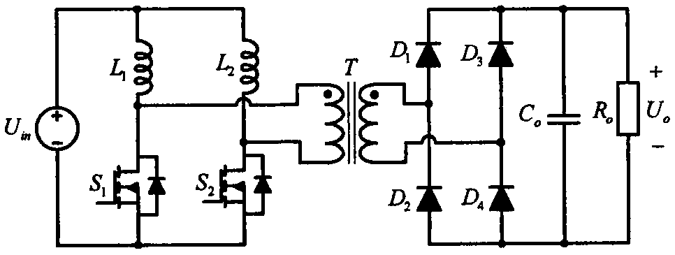
[0003] The traditional isolated DC converter realizes various boosting functions by adjusting the transformation ratio of the transformer. However, the following problems exist in simply relying on adjusting the transformation ratio of the transformer to realize the voltage boost: the voltage stress of the switching device is high, especially the converter secondary The voltage stress of the side rectifier diode is much higher than the output voltage; the leakage inductance of the transformer increases, causing voltage spikes and oscillations of the switching device, further aggravating the stress of the switching device, reducing reliability and efficiency
The main problem of this solution is that the rectifier circuit and non-isolated boost circuit on the secondary side of the transformer are all hard switches, and two-stage power conversion is required from input to output, which will greatly reduce the overall efficiency of the converter.

Method used


Image

  • Dual-voltage amplifying high-gain high-frequency rectifying isolating converter
  • Dual-voltage amplifying high-gain high-frequency rectifying isolating converter
  • Dual-voltage amplifying high-gain high-frequency rectifying isolating converter

Examples


Embodiment Construction

[0023] The technical solution of the present invention will be described in detail below in conjunction with the accompanying drawings.

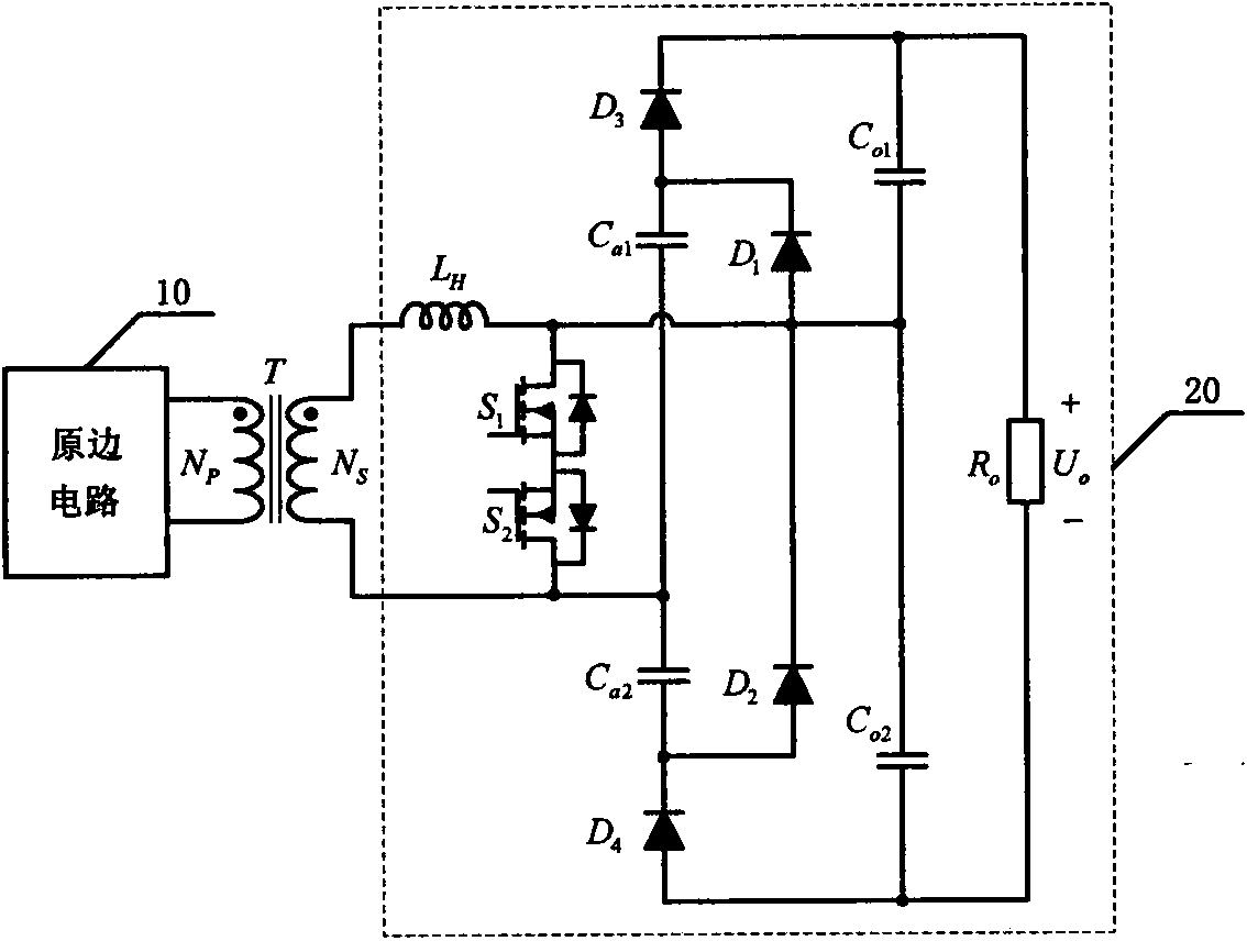
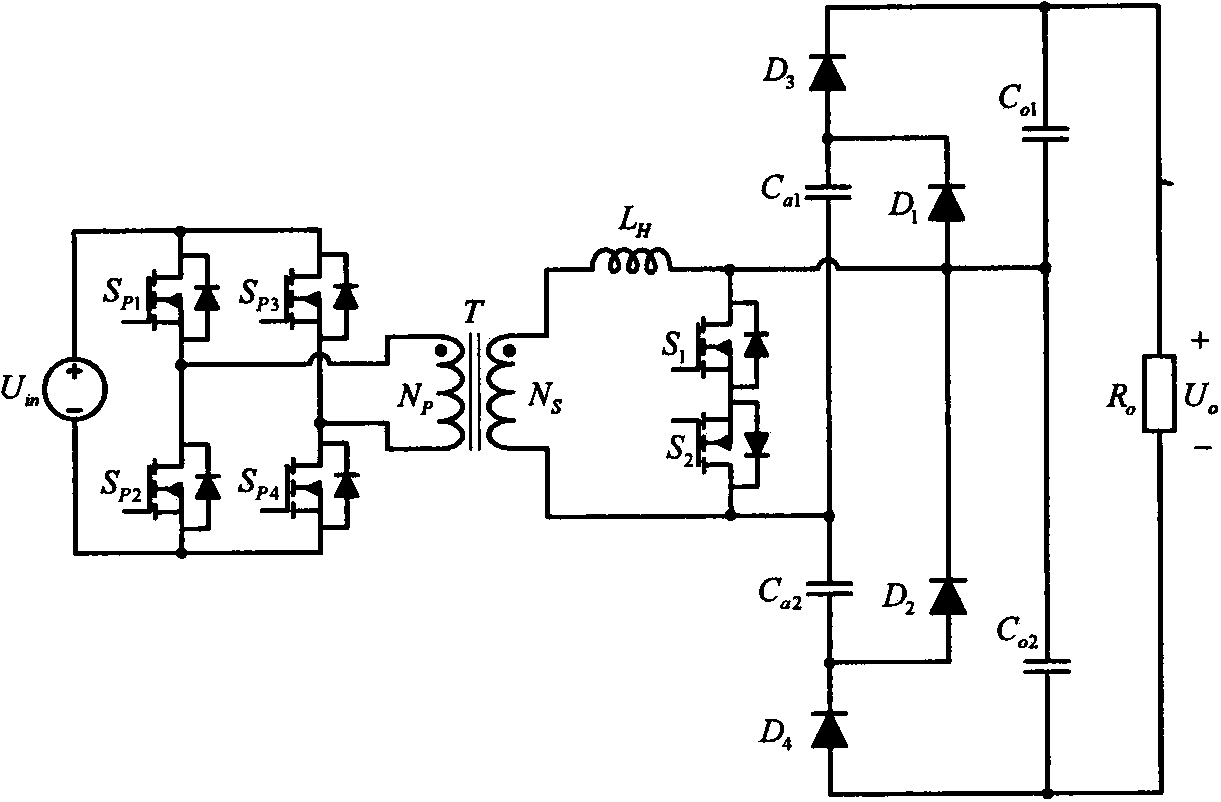
[0024] as attached figure 2 As shown, the double-voltage high-gain high-frequency rectification isolation converter is composed of a primary circuit (10), a transformer (T) and a rectification circuit (20), wherein the transformer (T) includes a secondary winding (N S ) and a primary winding (N P ), the rectifier circuit (20) consists of a high-frequency inductor (L H ), the first switching tube (S 1 ), the second switching tube (S 2 ), the first auxiliary capacitor (C a1 ), the second auxiliary capacitor (C a2 ), the first diode (D 1), the second diode (D 2 ), the third diode (D 3 ), the fourth diode (D 4 ), the first output filter capacitor (C o1 ), the second output filter capacitor (C o2 ) and load (R o ) composition; the transformer (T) secondary winding (N S ) is connected to the high frequency inductor (L H ) at one end...


PUM


Abstract

The invention discloses a dual-voltage amplifying high-gain high-frequency rectifying isolating converter and belongs to the technical field of power electronic converters. The dual-voltage amplifying high-gain high-frequency rectifying isolating converter is composed of a primary circuit, a transformer and a rectifying circuit. The rectifying circuit is composed of four diodes, two switch tubes, two auxiliary capacitors, two output filter capacitors, a high-frequency inductor and a load. According to the dual-voltage amplifying high-gain high-frequency rectifying isolating converter, a rectifying circuit has the controllable boosting and rectifying ability through the high-frequency inductor and the switch tubes, an embedded voltage amplifying rectifying circuit is formed through the auxiliary capacitors and the diodes, and a voltage amplifying output circuit is formed through the two output capacitors; in this way, the dual-voltage amplifying high-gain high-frequency rectifying isolating converter has the high-gain boosting and rectifying ability, soft switching of all the switch tubes and the diodes is achieved by the rectifying isolating converter through the high-frequency inductor, switching loss can be effectively reduced, efficiency can be improved, and the dual-voltage amplifying high-gain high-frequency rectifying isolating converter is particularly suitable for efficient high-gain isolating boosting direct-current power conversion occasions.

Description

technical field [0001] The invention relates to a double-voltage, high-gain, high-frequency rectification and isolation converter, which belongs to the technical field of power electronic converters, in particular to the technical field of isolated DC-DC power conversion. Background technique [0002] In applications in technical fields such as medical care, automobiles, aviation, aerospace, and renewable energy generation, for safety reasons and to meet voltage requirements, isolated step-up DC converters are usually required. How to increase the voltage gain of the isolated converter, reduce the voltage stress of the devices used in the converter, and realize high-efficiency power conversion has always been a key issue in this technical field. [0003] The traditional isolated DC converter realizes various boosting functions by adjusting the transformation ratio of the transformer. However, the following problems exist in simply relying on adjusting the transformation rati...

Claims


Application Information

Patent Timeline
Patent Type & Authority Applications(China)
IPC IPC(8): H02M3/335H02M7/217
Inventor 吴红飞夏天邢岩许鹏
Owner NANJING UNIV OF AERONAUTICS & ASTRONAUTICS
Learn More