LED drive circuit and method based on voltage memory and segmented current limiting

A LED driving and rectifying circuit technology, applied in the direction of electric lamp circuit layout, electric light source, lighting device, etc., can solve the problems of dim light string brightness, current fluctuation, LED chip damage, etc., to avoid dim brightness, good over-current protection, Effect of improving luminous efficiency

Active Publication Date: 2014-07-02
SOUTH CHINA UNIV OF TECH
View PDF5 Cites 4 Cited by
  • Summary
  • Abstract
  • Description
  • Claims
  • Application Information

AI Technical Summary

Problems solved by technology

[0004] The segmented LED drive circuit described above does not require electrolytic capacitors for voltage energy storage, the power factor is high, and the life of the entire lamp will not be limited by capacitors. However, this driving method also has shortcomings, which can be seen from the volt-ampere characteristics of LED devices. Under its normal working voltage condition, small differences in voltage will lead to obvious fluctuations in current, and the light intensity of LED is mainly related to the current flowing through LED; in practical applications, even if the LED chips produced by the same manufacturer in the same batch, There will also be differences in the volt-ampere characteristic curve, so the segmented driving method based on the fixed voltage division ratio, due to the reference voltage accuracy used for comparison and the difference in the volt-ampere characteristic of the LED chip, the working current of the LED in the light string cannot be determined. Accurate prediction and design, under-current or over-current driving status
Undercurrent will cause the brightness of the light string to be dim, while overcurrent will cause damage to the LED chip

Method used


Image

  • LED drive circuit and method based on voltage memory and segmented current limiting
  • LED drive circuit and method based on voltage memory and segmented current limiting
  • LED drive circuit and method based on voltage memory and segmented current limiting

Examples


Embodiment 1

[0032] The present invention will be described in further detail below in conjunction with the embodiments and accompanying drawings, but the embodiments of the present invention are not limited thereto.

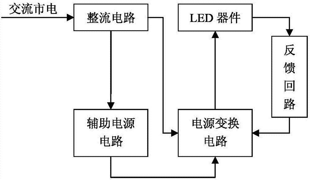
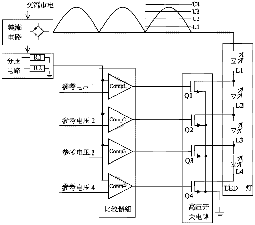
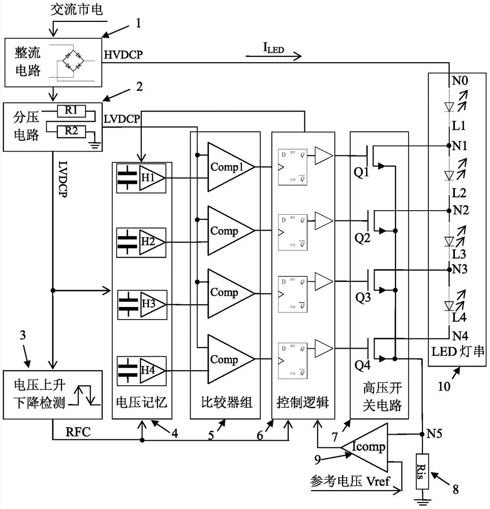
[0033] Such as image 3 As shown, the LED drive circuit based on voltage memory and segmental current limiting in this embodiment includes a rectifier circuit 1, a voltage divider circuit 2, a voltage rise and fall detection module 3, a voltage memory module 4, a comparator group 5, a control logic module 6, High-voltage switch circuit 7, current-sensing resistor 8 (Ris), current-sensing comparator 9 (Icomp) and LED light string 10; the voltage rise and fall detection module 3 is composed of a differential unit circuit and a voltage comparator; the voltage memory module 4 is composed of 4 voltage holders, numbered from top to bottom are H1, H2, H3 and H4, each of the voltage holders is composed of a capacitor and an operational amplifier; the comparator group 5 is composed o...


PUM


Abstract

The invention discloses an LED drive circuit and method based on voltage memory and segmented current limiting. The circuit comprises a rectifying circuit, a voltage division circuit, a voltage increasing and reducing detection module, a voltage memory module, a comparator set, a control logic module, a high-voltage switch circuit, a detection resistor, a current detection comparator and an LED lamp string. According to the drive method of the circuit, according to the increasing and reducing characteristics of the directly-rectified direct-current ripple voltages, the segmented type lightening control mode is adopted in the load of the LED lamp string. The drive circuit solves the problem of the influence of the difference of voltage current characteristics of an LED chip adopted by the lamp string in the actual application on drive currents, the work current of the LED lamp string in the whole work period is limited within the designed largest current value Imax, the problems of lower brightness caused by undercurrents and damage, caused by overcurrents, to the LED chip are solved, the light-emitting efficiency of the LED lamp is improved, and meanwhile overcurrent protection can be carried out on an LED device well.

Description

technical field [0001] The present invention relates to an LED drive circuit and method, in particular to an LED drive circuit and method that utilizes DC pulsating voltage directly rectified by AC mains for power supply, uses voltage memory and section current limiting, and belongs to the technical field of LED drive . Background technique [0002] The LED lighting drive circuit is the power supply circuit required to enable the lighting equipment using LEDs as light-emitting devices to work normally, and can provide the required voltage and current for the normal operation of the LED device. LED lighting drive circuit structure framework such as figure 1 As shown, it is mainly composed of a rectifier circuit, an auxiliary power supply circuit, a power conversion circuit and a feedback loop. The input AC power is transformed into DC high voltage by the rectifier circuit, and the DC high voltage is generated by the auxiliary power supply circuit to generate a stable DC low...

Claims


Application Information

Patent Timeline
Patent Type & Authority Applications(China)
IPC IPC(8): H05B37/02
CPCY02B20/42Y02B20/40
Inventor 梁志明詹建新李国元吴朝晖
Owner SOUTH CHINA UNIV OF TECH
Why Eureka
Try Eureka