Blow pipe handle of air compressor

An air compressor and handle technology, which is used in mechanical equipment, machines/engines, liquid variable capacity machines, etc., can solve the problems of difficult cleaning, excessive airflow, flying debris, etc. Effect

Active Publication Date: 2014-07-09
JINLING INST OF TECH
View PDF7 Cites 3 Cited by
  • Summary
  • Abstract
  • Description
  • Claims
  • Application Information

AI Technical Summary

Problems solved by technology

[0002] Before concrete pouring, it is often necessary to clean up the sawdust and other sundries on the formwork. Since most of the plate reinforcements have been bundled at this time, there are also great difficulties in conventional cleaning. The current method is to use air pressure The machine is connected to the blowpipe through a rubber hose to achieve the purpose of blowing out the sundries in the formwork. However, most of the existing blowpipes are single-piece tubular structures, and the airflow at the air outlet end cannot be adjusted. Therefore, excessive airflow often occurs. Phenomenon that the debris flies around and the airflow passes through the debris with a small mass and slightly larger mass

Method used


Image

  • Blow pipe handle of air compressor
  • Blow pipe handle of air compressor

Examples


Embodiment Construction

[0011] In order to make the technical means, creative features, goals and effects achieved by the present invention easy to understand, the technical solutions in the embodiments of the present invention will be clearly and completely described below in conjunction with the accompanying drawings in the embodiments of the present invention.

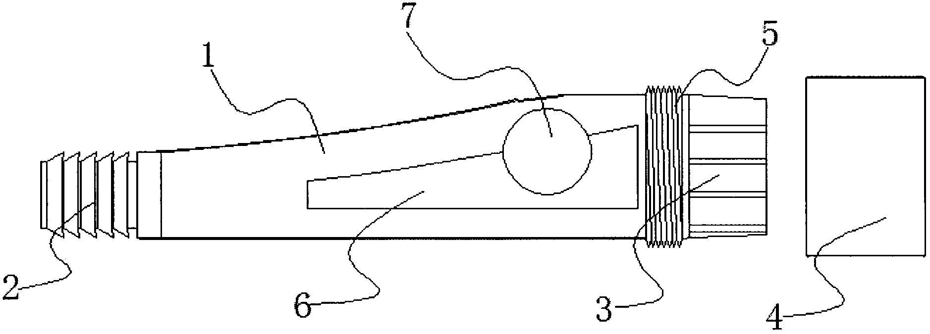
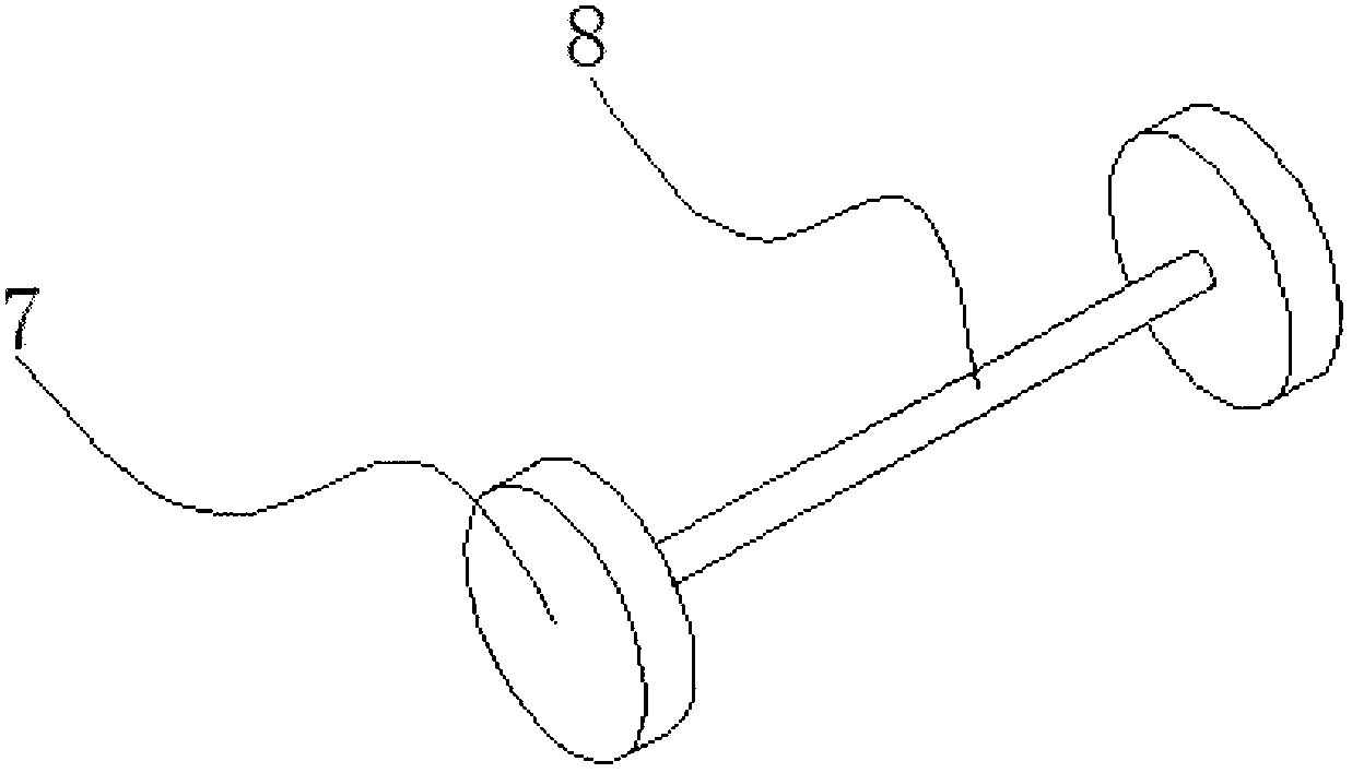
[0012] see Figure 1-2 , the specific embodiment is realized by adopting the following technical scheme, which includes a handle 1 connected between the rubber hose and the blowpipe, one end of the handle 1 is provided with an interface 2 connected with the blowpipe, and the other part of the handle 1 One end is provided with a fastener 3 and a threaded sleeve 4 which is socketed and matched with it. The front end of the fastener 3 is provided with a circle of external threads 5 matching the internal thread of the threaded sleeve 4. Both sides of the handle 1 The mirror image is provided with an adjustment groove 6, and an adjustment shaft...


PUM


Abstract

The invention discloses a blow pipe handle of an air compressor. The blow pipe handle of the air compressor comprises a handle connected between a rubber hose and a blow pipe, a connector connected with the blow pipe is formed in one end of the handle, a fastening piece and a barrel in sleeve fit with the fastening piece are mounted at the other end of the handle, a circle of external thread matched with an internal thread of the sleeve is formed in the front end of the fastening piece, each of two sides of the handle is longitudinally opened with an adjusting groove, an adjusting shaft is mounted in the adjusting groove, the height of the adjusting shaft is matched with the outer diameter of the handle, and an adjusting button is mounted at each of two ends of the adjusting shaft. The blow pipe handle of the air compressor is simple in structure, convenient to use, capable of effectively controlling the air output, and capable of being regulated according to the practical situation of the sundries in blowing.

Description

technical field [0001] The invention relates to the field of air compressor processing and manufacturing, in particular to a blowpipe handle of an air compressor. Background technique [0002] Before concrete pouring, it is often necessary to clean up the sawdust and other sundries on the formwork. Since most of the plate reinforcements have been bundled at this time, there are also great difficulties in conventional cleaning. The current method is to use air pressure The machine is connected to the blowpipe through a rubber hose to achieve the purpose of blowing out the sundries in the formwork. However, most of the existing blowpipes are single-piece tubular structures, and the airflow at the air outlet end cannot be adjusted. Therefore, excessive airflow often occurs. The phenomenon that debris flies around and the airflow passes through small and slightly larger debris and cannot be blown away. Contents of the invention [0003] The object of the present invention is ...

Claims


Application Information

Patent Timeline
Patent Type & Authority Applications(China)
IPC IPC(8): B08B5/02F04B39/00
CPCB08B5/02F04B39/00
Inventor 王书明薛涛陈葶葶曾庆林李幽静
Owner JINLING INST OF TECH
Why Eureka
Try Eureka