

Mask plate
A mask and area technology, applied in the field of mask, can solve the problems of poor product quality, high cost, defectiveness, etc., and achieve the effect of reducing sag, reducing height and tight adhesion
- Summary
- Abstract
- Description
- Claims
- Application Information
AI Technical Summary
Problems solved by technology
Method used
Image

Examples
Embodiment 2
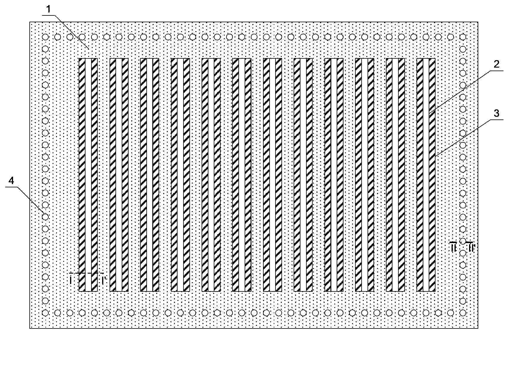
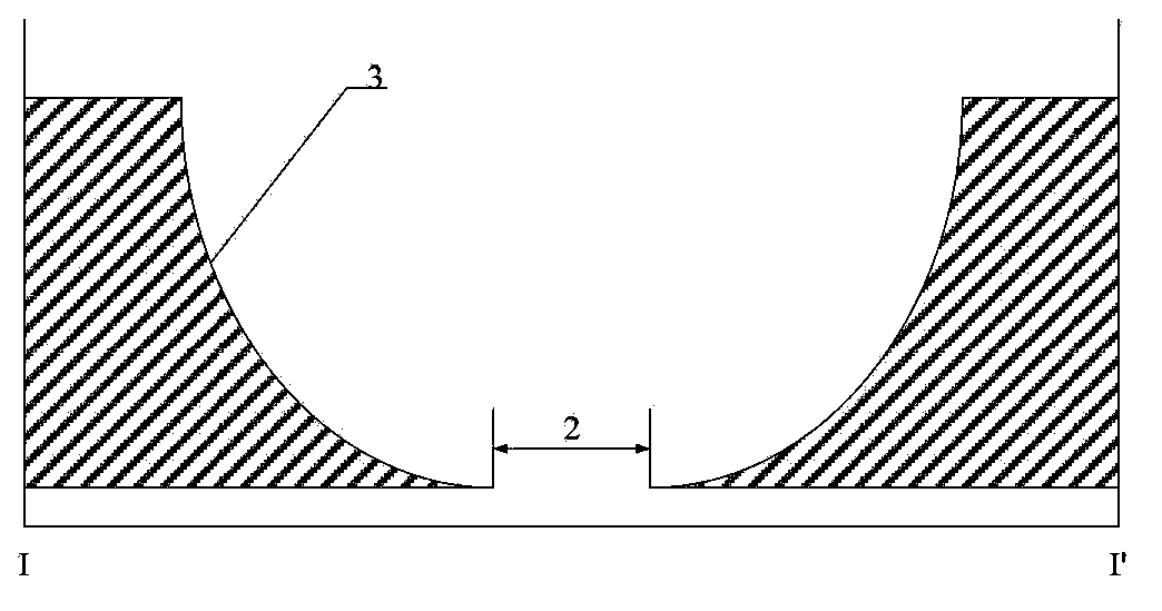
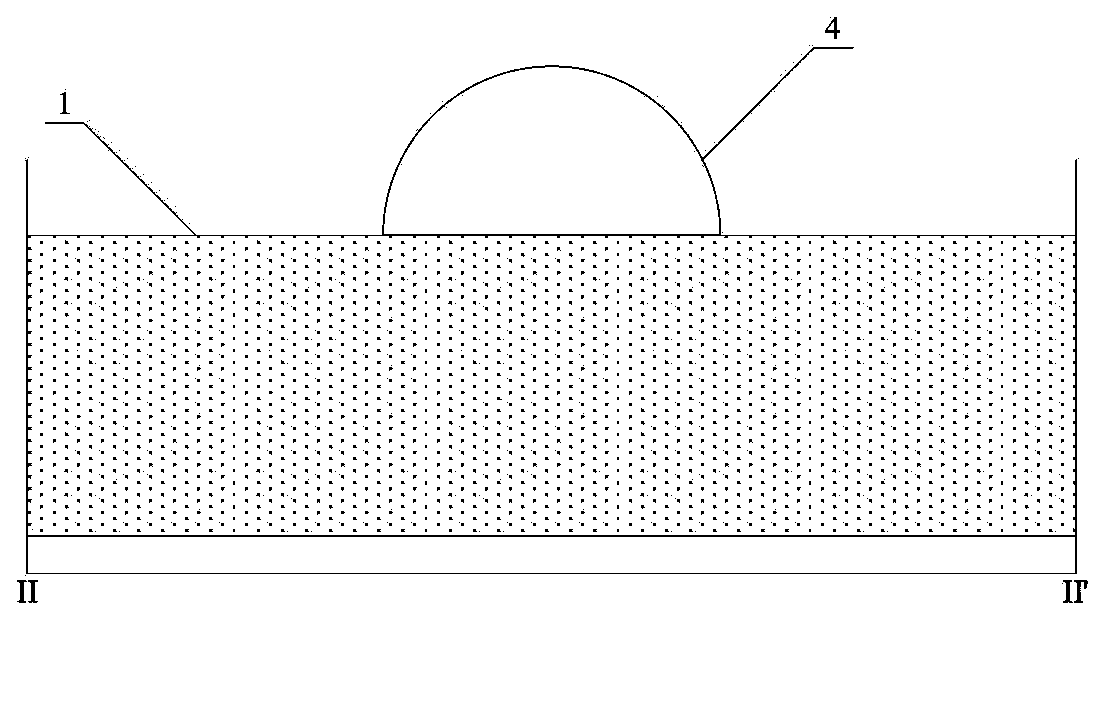
[0031] The mask plate 1 in the second embodiment is made of iron-nickel alloy material, which includes: an opening part (or opening) 2'; a shielding part 3'; a solder joint 4; a first groove 6; and a second groove 5. Figure 8 shown as Figure 4 Schematic diagram of the cross-section of the structure of Ⅳ-Ⅳ′. combine Figure 7 and Figure 8 It can be seen that the second groove 5 is arranged on the side of the mask 1 facing away from the substrate, and it is arranged at the welding spot 4 on the edge of the mask 1 , and the welding spot 4 is located in the second groove 5 . Described second groove 5 can accommodate one or more solder joints, and its short side length is slightly greater than the diameter of solder joint 4, and its long side length is greater than the sum of one or more solder joint 4 diameters, and its depth is greater than the diameter of solder joint 4. The height is generally in the range of 10um-20um, preferably 15um. The existence of the second groove...
PUM
 Abstract
Description
Claims
Application Information