

Powder spreading apparatus for selective laser melting
A technology of laser melting and powder spreading device, which is applied in metal material coating process, coating, etc., can solve the problems of low efficiency, high energy consumption of powder spreading, long moving path of powder spreading scraper, etc. The energy consumption of powder spreading and the effect of improving the efficiency of powder spreading
Active Publication Date: 2014-07-09
CHONGQING UNIV
View PDF4 Cites 12 Cited by
- Summary
- Abstract
- Description
- Claims
- Application Information
AI Technical Summary
Problems solved by technology
Powder spreading is an important part of selective laser melting. Using powder spreading to ensure the levelness and uniformity of the powder layer is a commonly used solution for metal powder laser melting forming systems. The powder spreading effect affects the compactness of the powder, and then It directly affects the molding quality of the parts. During the powder spreading process, the compactness of the powder is related to factors such as the flow of the powder and the pressure it receives. The powder spreading device in the prior art generally includes a powder supply bin, a processing bin, a recovery bin and Powder spreading scraper, in which the bottom of the processing chamber is the processing platform, through the rise of the bottom of the powder supply chamber, the lowering of the processing platform and the horizontal movement of the scraper, the powder supply and powder spreading are realized, and the excess powder is scraped on the processing plane to eliminate excess powder. The powder is scraped into the recovery bin. The disadvantages are: the powder supply bin, the processing bin and the recovery bin are arranged along the same horizontal plane, the overall structure space is large, the movement path of the powder spreading scraper is long, and it takes a long time for the scraper to complete a powder spreading. Moving back and forth produces an empty stroke, resulting in high energy consumption and low efficiency of powder spreading. At the same time, the metal powder in the powder supply bin is in a natural accumulation state, and the top layer of powder in the powder supply bin is always used as the source of powder spreading. This part of the metal powder The pressure is small, and the powder density is poor, which affects the molding quality of parts
Method used
View moreImage
Smart ImageViewing Examples

Examples
example
[0037]
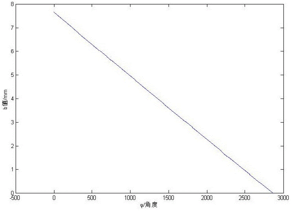
[0038] Drawing by matlab software Such as image 3 :
[0039] pass image 3 It can be seen that the corresponding powder flow gap b value can be obtained by rotating the angle instrument panel at different angles, and the linearity is good. As shown in the following table:
[0040]
Login to View More PUM
 Abstract
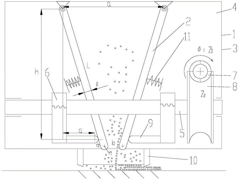
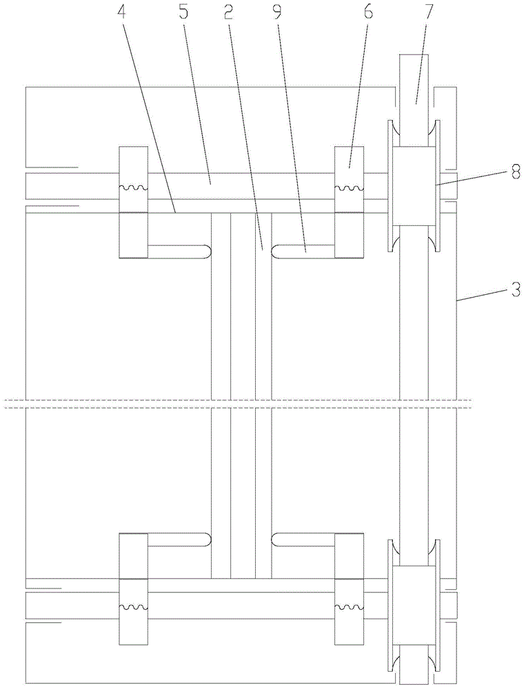
The invention discloses a powder spreading apparatus for selective laser melting. The apparatus comprises a funnel-type powder spreading bin used for holding powder to be spread and an adjusting device used for adjusting at least pressure of powder located at the powder outlet of the funnel-type powder spreading bin. According to the invention, the powder spreading bin with a funnel-type structure is employed and arranged along a vertical direction together with a processing platform; compared with the prior art, the powder spreading apparatus provided by the invention has a simple and compact structure, is free of idle stroke during round-trip powder spreading and can save driving energy needed in movement of the powder spreading apparatus, reduce energy consumption in powder spreading and improve powder spreading efficiency; powder at the bottom of the funnel-type powder spreading bin is used as a spreading powder source and has great pressure due to extrusion, so powder spreading compactness can be improved, thereby further improving part forming quality; the powder spreading bin can be also applied in research of powder fluidity and can effectively measure influence of a variety of factors on compactness of spread powder.
Description
technical field [0001] The invention relates to the technical field of metal powder laser melting forming, in particular to a selective laser melting powder spreading device. Background technique [0002] Metal powder laser melting forming system, also known as 3D printer, has attracted widespread attention because of its ability to form complex metal parts that can be used directly, and is predicted to be one of the key technologies that may trigger the "third industrial revolution". Powder spreading is an important part of selective laser melting. Using powder spreading to ensure the levelness and uniformity of the powder layer is a commonly used solution for metal powder laser melting forming systems. The powder spreading effect affects the compactness of the powder, and then It directly affects the molding quality of the parts. During the powder spreading process, the compactness of the powder is related to factors such as the flow of the powder and the pressure it recei...
Claims
Login to View More Application Information
Patent Timeline
 Patent Type & Authority Applications(China)
IPC IPC(8): C23C24/10
Inventor 张正文刘飞李忠华傅广徐华鹏
Owner CHONGQING UNIV