A washing and drying machine

A washing and drying machine and integrated technology, applied in the field of drying, can solve the problems of reducing the drying capacity of the cavity to be dried, reducing the drying efficiency of the condensation drying device, and occupying space for the condenser, so as to save raw materials, dry Increased dry capacity and good assemblability

Active Publication Date: 2017-02-08
SUZHOU SAMSUNG ELECTRONICS CO LTD +1
View PDF6 Cites 0 Cited by
  • Summary
  • Abstract
  • Description
  • Claims
  • Application Information

AI Technical Summary

Problems solved by technology

[0005] In the condensation drying device with the above structure, since the condenser and the cavity to be dried are of a split structure, and the condenser will occupy a specific space
And the size of the condensing and drying device needs to meet the professional requirements of a specific industry. Based on this premise, the drying capacity of the cavity to be dried is reduced while ensuring that the condensing and drying device is in a specific volume.
On the other hand, in order to ensure the drying capacity of the condensing and drying device, the volume of the condenser of the condensing and drying device is usually reduced, but because the volume of the condenser is reduced, the drying efficiency of the condensing and drying device will be correspondingly reduced. reduce

Method used


Image

  • A washing and drying machine
  • A washing and drying machine
  • A washing and drying machine

Examples


Embodiment 1

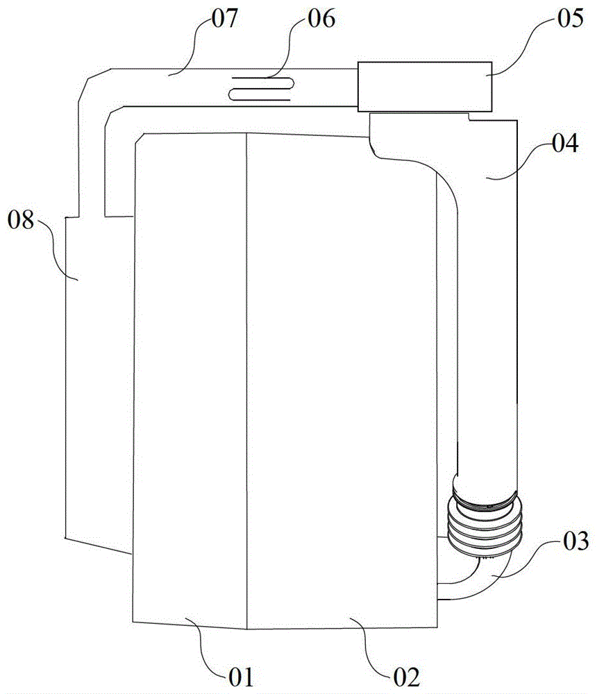
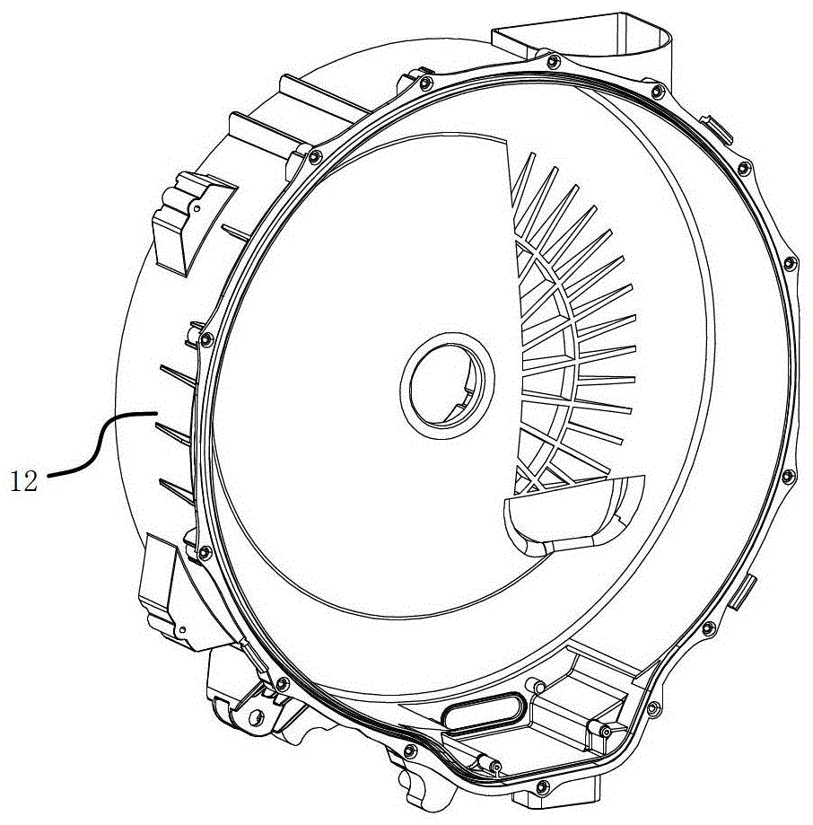
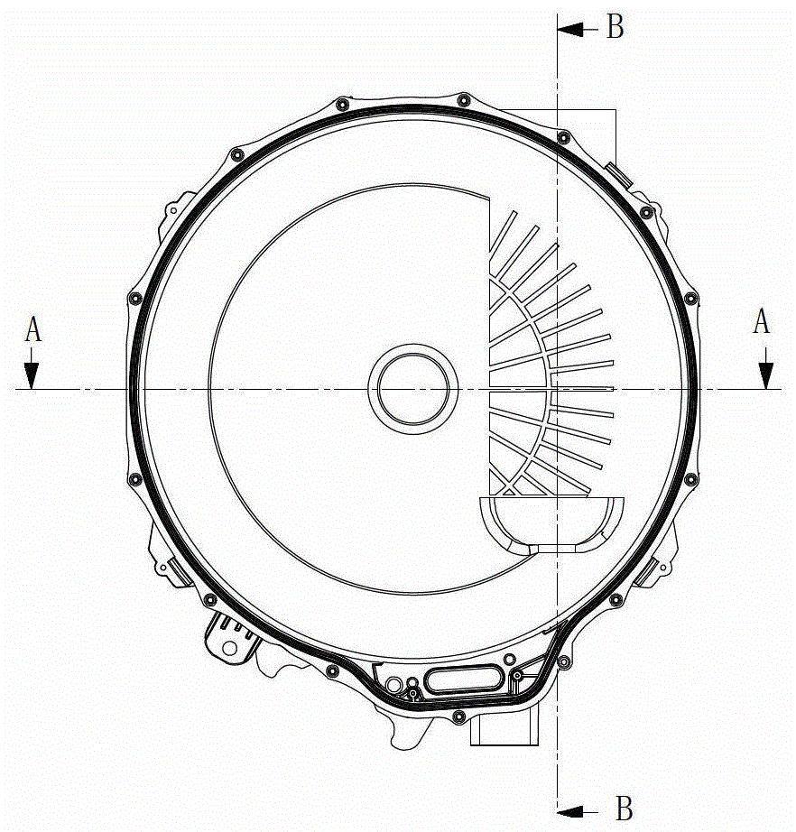
[0036] ginseng Figure 2 to Figure 8 As shown, the rear barrel 12 is the same part as the condenser 16 . The condenser 16 is a hollow cavity with an air inlet 16a and an air outlet 16b. The condenser 16 occupies the space of the rear rib of the rear barrel 12 .

[0037] During the forming process of the rear cylinder 12, the corresponding mold forms the condenser space. The rear barrel mold includes a first mold unit 18a, a second mold unit 18b and a condenser mold 18c. The first mold unit 18 a forms the space for accommodating the inner cylinder of the rear cylinder 12 , and the second mold unit 18 b forms the cylinder wall of the rear cylinder 12 . The first mould unit 18a further includes a condenser air inlet mould structure 18d for forming the air inlet of the condenser. The condenser mould 18c forms the condensation cavity of the condenser 16, the first mould unit 18a and the condenser mould 18c form the condenser wall of the condenser 16 close to the inner cylinder ...

Embodiment 2

[0040] A part of the cylinder wall of the rear cylinder and the condenser cover together form a condensation cavity, and the condensation cavity has an air inlet and an air outlet. The condenser occupies the space of the stiffener at the rear of the rear barrel. The condenser cover is a piece of space. The condenser cover is fastened to the rear cylinder. The rear barrel mold includes a first mold unit, a second mold unit, and a condenser mold. The first mold unit mainly forms the space of the rear barrel for accommodating the inner barrel, and the second mold unit forms the barrel wall of the rear barrel. The first mould unit and the second mould unit together form part of the cylindrical wall of the condenser, which together with the condenser cover forms the condenser. The first mould unit, the second mould unit and the condenser mould together form the air outlet and the condensation cavity of the condenser.

[0041] Compared with the traditional solution, this solutio...

Embodiment 3

[0043] The condenser is a pre-formed hollow tubular structure. The condenser is injection-molded into one body through an integral molding process with the rear barrel, and the condenser occupies the space of the reinforcing rib at the rear of the rear barrel. The condenser includes an air inlet and an air outlet. The rear barrel mold includes a first mold unit, a second mold unit and a condenser mold. A pre-formed condenser can be fitted to the outside of the condenser mould.

[0044] Before the injection of the rear barrel, the pre-molded condenser is first placed in the condenser mold, and then the injection is started. The first mold unit is filled in the accommodating space of the rear barrel, the second mold unit is surrounded by the outside of the first mold unit, and a certain injection molding space is reserved between the first mold unit and the second mold unit to form the barrel wall of the rear barrel by injection molding, The condenser mold is filled into the ...


PUM


Abstract

The invention discloses a clothes washing and drying machine. The clothes washing and drying machine comprises an inner cylinder, an outer cylinder, and a drying assembly communicated with the inner cylinder and the outer cylinder; the drying assembly comprises a condenser and a dryer; the dryer comprises a circulating fan and a heater both arranged in the dryer, the condenser comprises an air inlet and an air outlet, and a condensation cavity formed by the inner walls of the condenser, the outer cylinder comprises a front cylinder and a rear cylinder, the two of which are fixedly connected with each other, and the rear cylinder and the condenser are formed into an integrated structure by using a rear cylinder mold and a condenser module and an integrated processing manner. The clothes washing and drying machine is characterized in that apart from heat exchange happening inside the condenser, the temperature of one side, close to a drying material receiving assembly, of the condenser is higher than the temperature in the drying material receiving assembly, so that heat exchange also happens on the surface of the condenser and water drops are formed on the surface, and therefore, high heat exchange efficiency of the condenser is guaranteed. Meanwhile, when the clothes washing and drying machine is arranged in a case of the same size, the drying capacity of the clothes washing and drying machine with such a structure can be improved to a certain extent.

Description

technical field [0001] The present invention relates to the technical field of drying, and more particularly, to a washing and drying machine. Background technique [0002] Drying refers to the process of removing the solvent content in the solid material in some way. It usually refers to the process of evaporating and taking away the solvent in the solid material by introducing hot air. The drying process is widely used in daily life, textile industry, chemical industry, pharmaceutical industry, construction industry and other industries, such as drying daily items, textiles, food, medicinal materials, wood, building materials, cardboard, etc., devices for drying the above materials It came into being, such as condensation drying device for drying utensils, condensation drying device for drying textile products, condensation drying device for drying food, condensation drying device for drying medicinal materials, Condensation drying units for drying sheets, etc. [0003]...

Claims


Application Information

Patent Timeline
Patent Type & Authority Patents(China)
IPC IPC(8): D06F58/02D06F58/04
CPCD06F25/00D06F58/04D06F58/24
Inventor 于军蕾
Owner SUZHOU SAMSUNG ELECTRONICS CO LTD
Why Eureka
Try Eureka