Rotor high-low pressure power device and work doing method of rotor high-low pressure power device

A power equipment, high and low pressure technology, applied in the field of thermal power equipment, can solve the problems of complex structure, high manufacturing cost and high cost of internal combustion engine radial engine, and achieve the effects of light weight, high running speed and small vibration

Inactive Publication Date: 2014-07-09
郭远军
View PDF2 Cites 13 Cited by
  • Summary
  • Abstract
  • Description
  • Claims
  • Application Information

AI Technical Summary

Problems solved by technology

[0017] The invention overcomes the problems of high cost of the expansion chamber, compression chamber, heater, cooling chamber, regenerator, etc. in the external combustion engine, and the heat loss is 2-3 times that of the internal combustion engine; it overcomes the need for expansion in the organic Rankine cycle system Engine or steam turbine, the technical problem of high manufacturing cost; overcome the problem of complex structure and high manufacturing cost of internal combustion radial engine

Method used


Image

  • Rotor high-low pressure power device and work doing method of rotor high-low pressure power device
  • Rotor high-low pressure power device and work doing method of rotor high-low pressure power device

Examples


Embodiment 1

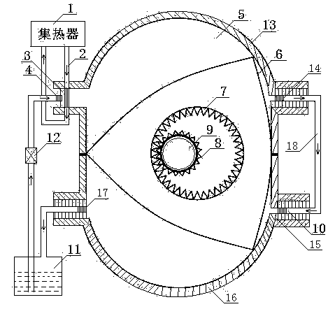
[0030] A rotor high and low pressure power equipment, including heat collector 1, heat preservation pipe 2, gasification reactor 3, atomizer 4, cylinder 5, triangular rotor 6, inner ring gear 7, gear 8, output shaft 9, one-way Air intake valve 10, liquid storage tank 11, pressure valve 12, insulation layer 13, automatic exhaust valve 14, casing 15, radiator 16, exhaust control valve 17 and buffer pipe 18; the casing 15 is provided with a triangular rotor 6. The center of the triangular rotor 6 is provided with an inner ring gear 7. The gear 8 matched with the inner ring gear 7 is fixed on the output shaft 9. The triangular rotor 6 divides the cylinder 5 into three uniform independent spaces. The inner ring gear 7 The ratio of the number of teeth to the gear 8 is 3:2; one side of the cylinder 5 is provided with a gasification reactor 3 and an exhaust control valve 17, and the other side of the cylinder 5 is provided with an automatic exhaust valve 14 and a one-way intake valve 1...

Embodiment 2

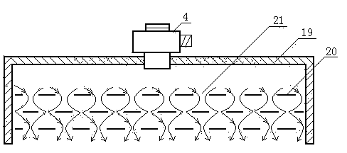
[0032] Like the rotor high and low pressure power equipment in Example 1, the gasification reactor 3 includes a pressure shell 19, a gasification heat conduction sheet 20, an air hole 21, and an atomizer 4, and the gasification heat conduction sheet 20 is arranged on the pressure shell 19, Air holes 21 are arrayed on the vaporization heat conducting sheet 29, and an atomizer 4 is provided at the inlet end of the pressure shell 19; the pressure valve 12 is associated with the output shaft 9, and the pressure valve opens and closes three times for each cycle completed.


PUM


Abstract

The invention relates to a rotor high-low pressure power device. The rotor high-low pressure power device comprises a heat collector, a heat preservation pipe, a gasification reactor, an atomizer, an air cylinder, a triangular rotor, an inner gear ring, a gear, an output shaft, a one-way air inlet valve, a liquid storage tank, a pressure valve, a heat preservation layer, an automatic air discharging valve, a device shell, a heat dissipation device and an air discharging control valve. The triangular rotor is arranged in the device shell, the inner gear ring and the gear matched with the inner gear ring are arranged in the center of the triangular rotor, the gear is fixed to the output shaft, the air cylinder is divided by the triangular rotor into three even independent spaces, and the ratio of the tooth number of the inner gear ring to the tooth number of the gear is 3:2. The rotor high-low pressure power device has the advantages that work is done three times when a rotor with a rotor engine rotates by a circle, and the horsepower volume ratio is high; the rotor high-low pressure power device is high in operation rotating speed, small in size, light in weight, low in gravity center and small in vibration; media are recycled, and pollution is avoided; the heat energy conversion efficiency ranges from 65% to 98%; conventional energy sources can be substituted, the economic benefits are high, energy is saved, and the rotor high-low pressure power device is environmentally friendly and low in noise.

Description

technical field [0001] The invention belongs to the field of thermal power equipment, in particular to a power machine that converts heat energy such as solar energy, geothermal heat, high-temperature gas generated by combustible combustion, internal combustion engine heat or exhaust gas, and high-temperature gas discharged from factories into kinetic energy. Background technique [0002] Traditional power equipment includes steam engine, internal combustion engine and external combustion engine. [0003] Steam engine: Inseparable from the boiler, the whole device is bulky and bulky; the pressure and temperature of the fresh steam cannot be too high, the exhaust pressure cannot be too low, and the thermal efficiency is difficult to improve; it is a reciprocating machine, and the inertia limits the increase of the speed; The working process is discontinuous, and the flow of steam is limited, which limits the improvement of power. [0004] Internal combustion engine: complex ...

Claims


Application Information

Patent Timeline
Patent Type & Authority Applications(China)
IPC IPC(8): F01K7/00F01K11/00F01C1/22F01C21/08F01K13/00
CPCF01K7/00
Inventor 郭远军
Owner 郭远军
Why Eureka
Try Eureka