Micro/nano-particle-filled optical microfluidic-chip biosensor
A technology of microfluidic chips and biosensors, applied in the field of refractive index testing, can solve problems such as not being good at testing surface refractive index, and achieve the effect of improving test stability
- Summary
- Abstract
- Description
- Claims
- Application Information
AI Technical Summary
Problems solved by technology
Method used
Image
Examples
example 1
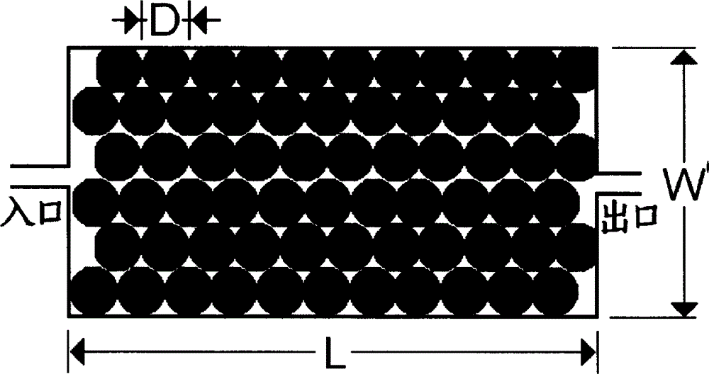
[0021] First, a structure such as figure 1 The shown microfluidic chip sensor, in which the material of the ball is glass.
[0022] Secondly, the aqueous solution is passed into the optical cavity first, and then the aqueous solution of the substance to be measured is passed through; the substance to be measured will be adsorbed on the inner wall of the cavity and the surface of the bead, thereby changing the overall average refractive index of the substance in the cavity, and the transmittance. The phase of the light wave in the cavity.
[0023] Finally, by testing the phase of the transmitted light wave, the refractive index and composition of the substance to be tested can be obtained.
example 2
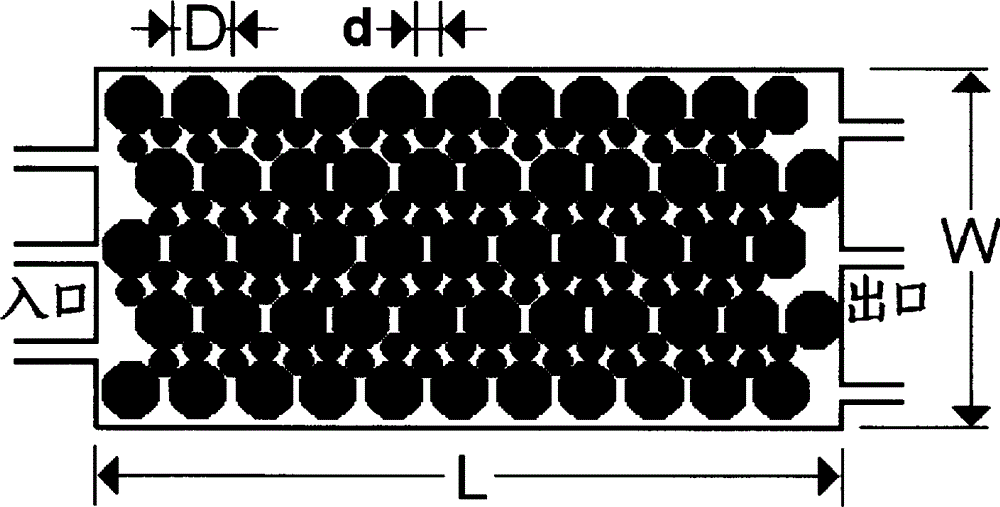
[0025] First, fabricate structures on glass substrates such as figure 2 The shown microfluidic chip sensor, in which the material of the ball is organic plastic.
[0026] Secondly, a solution such as dextran is first introduced into the optical cavity, and the dextran molecules will be adsorbed on the inner wall of the cavity and the surface of the bead to improve the adsorption capacity of the inner wall of the cavity and the surface of the bead; The substance to be tested will be adsorbed on the inner wall of the cavity and the surface of the bead, thereby changing the overall average refractive index of the substance in the cavity and the intensity of the light wave passing through the cavity.
[0027] Finally, by testing the intensity of the transmitted light wave, the refractive index and concentration of the substance to be tested can be obtained.
example 3
[0029] First, fabricate structures such as image 3 The shown microfluidic chip sensor, in which the material of the ball is quartz.
[0030] Secondly, the air is introduced into the optical cavity first, and then the air containing alcohol is introduced; the alcohol will be adsorbed on the inner wall of the cavity and the surface of the ball, thereby changing the overall average refractive index of the material in the cavity and the transmission rate through the cavity. The phase of the light wave.
[0031] Finally, by testing the phase of the transmitted light wave, the concentration of alcohol is known.
[0032] In summary, the optical microfluidic chip biosensor provided by the present invention can effectively increase the surface area of the cavity and the adsorption amount of the substance to be tested by filling the cavity with small balls, thereby greatly improving the test sensitivity.
PUM
 Abstract
Description
Claims
Application Information
 - R&D
- Intellectual Property
- Life Sciences
- Materials
- Tech Scout
- Unparalleled Data Quality
- Higher Quality Content
- 60% Fewer Hallucinations
Browse by: Latest US Patents, China's latest patents, Technical Efficacy Thesaurus, Application Domain, Technology Topic, Popular Technical Reports.
© 2025 PatSnap. All rights reserved.Legal|Privacy policy|Modern Slavery Act Transparency Statement|Sitemap|About US| Contact US: help@patsnap.com


