
Terminal block for electric meter

A technology for electric meters and bases, applied in the field of electric meters, to achieve the effects of firm fixation, short circuit design, and improved waterproof and dustproof performance

Active Publication Date: 2016-05-11
ANHUI YONG AN ELECTRONICS TECH CO LTD
View PDF10 Cites 0 Cited by
  • Summary
  • Abstract
  • Description
  • Claims
  • Application Information

AI Technical Summary

Problems solved by technology

[0004] In order to solve the above problems, the purpose of the present invention is to provide a terminal block for electric meters, which has few connecting wires, and integrates all external components in the base of the terminal block, which can realize integrated mechanical installation, simple process and stable Reliable, safe to use, low production cost, solves the problem of measurement distortion and meets product quality requirements

Method used


Image

  • Terminal block for electric meter
  • Terminal block for electric meter
  • Terminal block for electric meter

Examples


Embodiment Construction

[0019] In order to make the object, technical solution and advantages of the present invention clearer, the present invention will be further described in detail below in conjunction with the accompanying drawings and embodiments. It should be understood that the specific embodiments described here are only used to explain the present invention, not to limit the present invention.

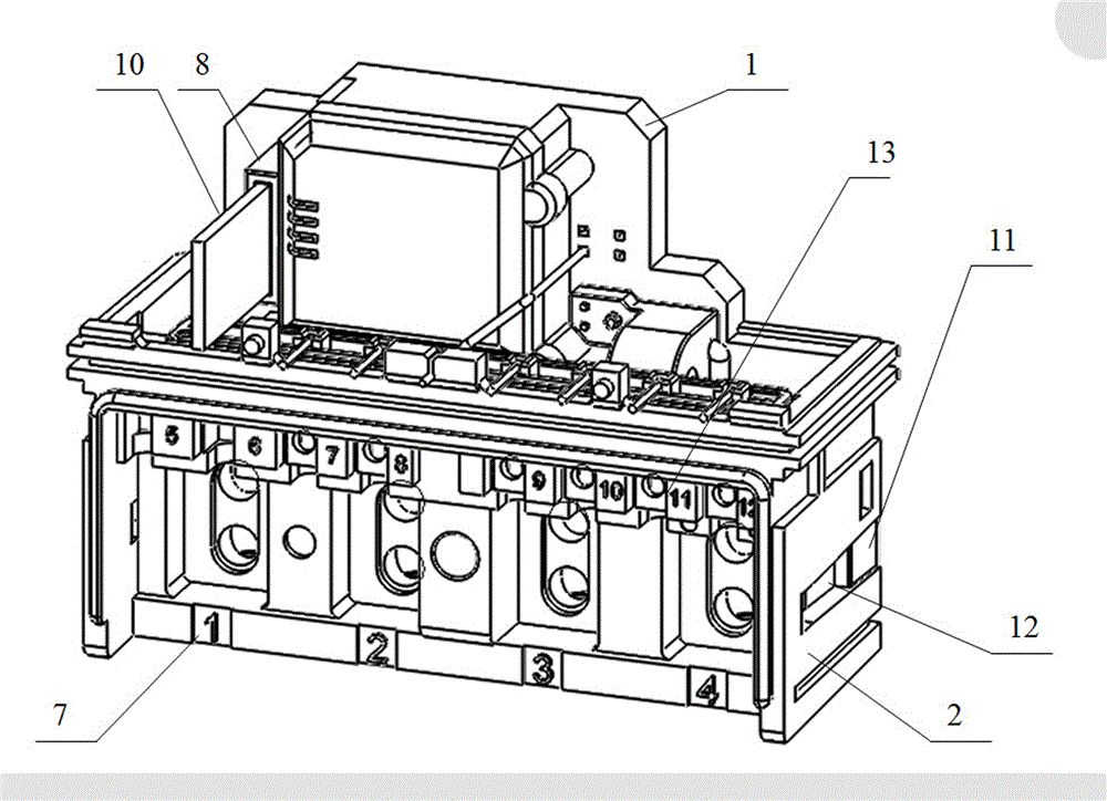
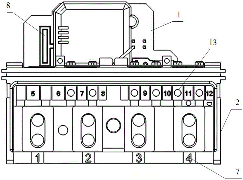
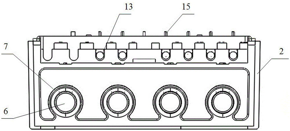
[0020] Depend on figure 1 — Figure 10 It can be seen that a terminal base for an electric meter in this embodiment includes a base 1 and an upper cover 2, and the surface of the base 1 is provided with a transformer installation station 3, a relay installation station 4, and a shunt installation station 5. Transformers, relays and shunts are correspondingly installed on the top, a plurality of input terminals 6 are provided at the bottom of the base 1, and corresponding wiring holes 7 are provided at the bottom of the upper cover 2 corresponding to the input terminals 6 of the base 1. The face o...


PUM


Abstract

The invention discloses a terminal base for an electric meter. The terminal base for the electric meter comprises a base body and an upper cover. A mutual inductor, a relay and a shunt are installed on all stations on the face of the base body respectively. A wiring board jack base with an inner slot is arranged on the face of the base body. A meter installation station is arranged on the back side of the base body, and a metering circuit template is installed on the back side of the base body. The metering circuit template is connected with a circuit function template on an external electric meter through the slot in the wiring board jack base by means of a PCB connection plate. Contact pins connected with a meter function template are fixedly installed on binding posts on the upper portion of the upper cover, and a fixing plate is installed at the position corresponding to the positions of the binding posts. The mutual inductor, the relay and the shunt on the base body are electrically connected with the circuit function template on the electric meter through the contact pins. According to the technical scheme, the terminal base for the electric meter is directly connected with a control unit through a wiring board in an inserted mode, the technology is simple, stability and firmness are achieved, use is safe, production cost is low, the problem of inaccurate measurement is solved, and the requirement for product quality is met.

Description

technical field [0001] The invention belongs to the technical field of electric meters, in particular to a terminal base for electric meters. Background technique [0002] The upper cover and the base of the existing electric meter terminal block are designed as one-piece inserts. Because the thermal expansion coefficients of plastic parts and copper materials are different, the inserts are prone to fall off under long-term work, resulting in product failure; there are many processing steps and Complex, it is not easy to automate and simplify the process; the integrated structure is lower than the waterproof level, it is difficult to meet the waterproof level of IP54 or higher, and it is easy to seepage. [0003] In addition, most of the various devices on the existing terminal block are connected to the functional template of the meter through wires. There are too many connecting wires, the circuit of the meter is too long, there are many hot spots, and there is a quality p...

Claims


Application Information

Patent Timeline
Patent Type & Authority Patents(China)
IPC IPC(8): G01R11/04
Inventor 沈辉江伟明王琦李国强
Owner ANHUI YONG AN ELECTRONICS TECH CO LTD
Learn More