
Solar cell and solar cell module group

A solar cell and electrode technology, applied in the field of solar cells, can solve the problems that the current density of the solar cell 100 cannot be effectively increased, the cell efficiency cannot be improved, and the efficiency of carrier collection is reduced.

Inactive Publication Date: 2014-07-09
MOTECH INDUSTRIES
View PDF3 Cites 2 Cited by
  • Summary
  • Abstract
  • Description
  • Claims
  • Application Information

AI Technical Summary

Problems solved by technology

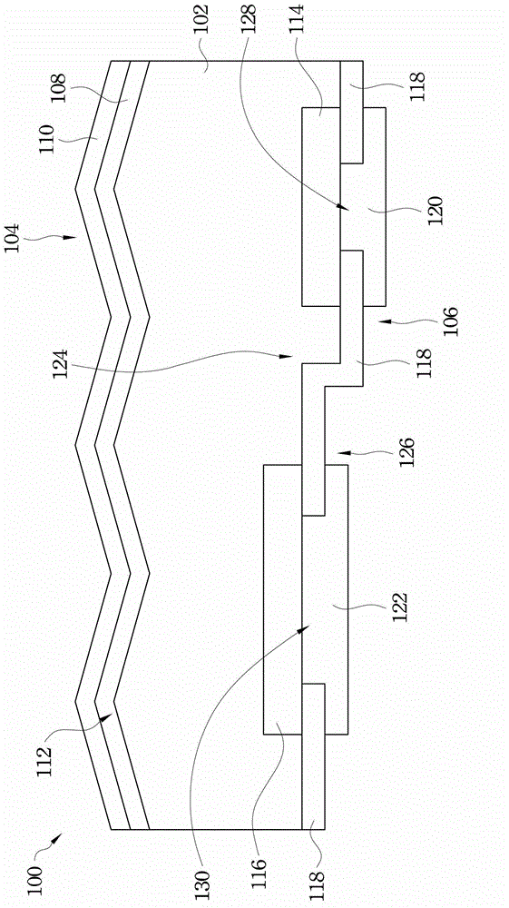
However, when carriers are formed on the light-receiving surface 104 of the N-type substrate 102 corresponding to the double-stage structure 124 on the other side, the derivation path of the carriers here can only go to the linear openings 128, 130 moves, which means that the distance between the N-type electrode 120 and the P-type electrode 122 in the openings 128 and 130 for carriers to move is longer, which will lead to a decrease in the efficiency of carrier collection, thereby making the current density of the solar cell 100 unable to Effectively improve, and lead to the problem that the overall battery efficiency cannot be improved

Method used


Image

  • Solar cell and solar cell module group
  • Solar cell and solar cell module group
  • Solar cell and solar cell module group

Examples


Embodiment Construction

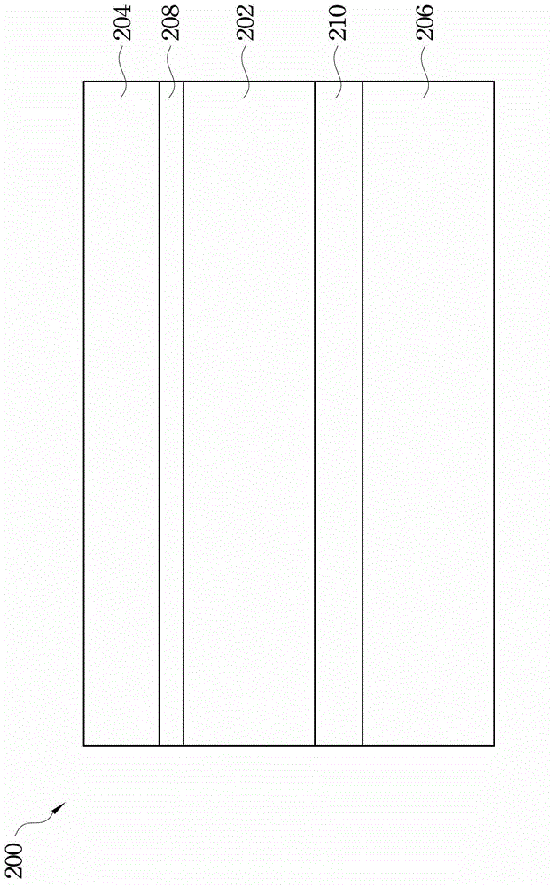
[0064] Please refer to figure 2 , which is a schematic cross-sectional view illustrating a solar cell module according to an embodiment of the present invention. In this embodiment, the solar cell module 200 mainly includes an upper plate 204, a lower plate 206, a solar cell 202, and one or more packaging material layers, such as packaging material layers 208 and 210, such as ethylene vinyl acetate copolymer (EVA) material.

[0065] Such as figure 2 As shown, in the solar cell module 200 , the solar cell 202 is disposed on the lower plate 206 and is disposed under the upper plate 204 . Therefore, the upper plate 204 is disposed on the lower plate 206 , and the solar cell 202 is disposed between the lower plate 206 and the upper plate 204 . In addition, the two packaging material layers 208 and 210 are respectively disposed between the upper plate 204 and the solar cell 202 , and between the lower plate 206 and the solar cell 202 . The encapsulation material layers 208 an...


PUM


Abstract

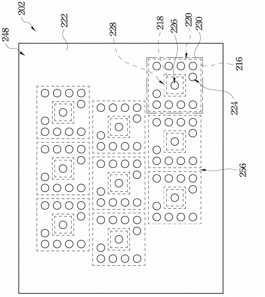
The invention discloses a solar cell and a solar cell module group. The solar cell includes a second conductive substrate, a plurality of first conductive layers and second conductive layers, a passivation layer, a plurality of first holes and second holes, a first electrode, and a second electrode. The second conductive substrate includes a light receiving side and a back side. The first conductive layers are arranged on the back side. The second conductive layers are arranged on the back side in a two-dimensional array manner and the second conductive layers are independent from each other and are not connected with each other. Each second conductive layer is enclosed by the first conductive layer. The passivation layer is arranged on the first conductive layers and second conductive layers. The first holes and second holes are arranged in the passivation layer and are corresponding to the first first conductive layers and second conductive layers. The first electrode and the second electrode are arranged on the passivation layer, and are respectively contacted with the first conductive layers via the first hole and with the second conductive layers via the second hole.

Description

technical field [0001] The present invention relates to a photoelectric conversion device, and in particular to a solar cell. Background technique [0002] Since an interdigitated back contact solar cell (IBC) has high cell efficiency, it has become a trend in the development of solar cells. Please refer to figure 1 , which is a partial cross-sectional view of an interdigitated back-contact solar cell. The interdigitated back-contacted solar cell 100 mainly includes an N-type substrate 102, N + Type conductive layer 108, anti-reflection layer 110, N ++ Type doped layer 114, P + type doped layer 116 , passivation layer 118 , N-type electrode 120 and P-type electrode 122 . [0003] In the solar cell 100 , the opposite sides of the N-type substrate 102 respectively have a light-receiving surface 104 and a back surface 106 . A rough structure 112 is provided on the light-receiving surface 104 to increase the amount of incident light. N + The conductive layer 108 is dispo...

Claims


Application Information

Patent Timeline
IPC IPC(8): H01L31/0224
CPCY02E10/50H01L31/022458
Inventor 陈亮斌
Owner MOTECH INDUSTRIES
Learn More