

Air-cooled integrated bipolar plate for fuel cells
A fuel cell and bipolar plate technology, applied in the direction of fuel cells, fuel cell additives, fuel cell heat exchange, etc., can solve the problems of inconsistency, less applicable environment, high air requirements, etc., to improve performance and life, and flexible shape design , flexible operation
- Summary
- Abstract
- Description
- Claims
- Application Information
AI Technical Summary
Problems solved by technology
Method used
Image

Examples
Embodiment 1
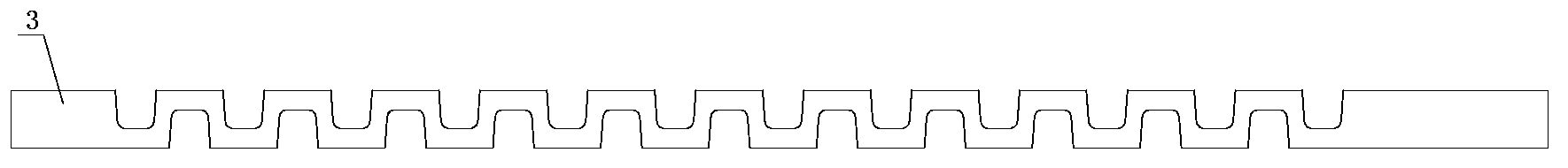
[0034] Such as Figure 4 As shown, an air-cooled integrated bipolar plate for a fuel cell includes a cathode plate 2 and an anode plate 7, the cathode plate and the anode plate are only provided with fuel inlet and outlet fluid holes and oxidant inlet and outlet fluid holes, and no cooling fluid inlet and outlet holes are provided. A layer of heat sink 3 is arranged between the cathode plate 2 and the anode plate 7, and a fluid channel 5 is arranged on the heat sink 3. The fluid channel 5 is formed by stamping an aluminum alloy plate, that is, parallel grooves with a trapezoidal cross section are stamped opposite to each other on both sides of the aluminum alloy plate. Such as figure 2 shown. A fuel fluid channel 4 is provided on the cathode plate 2 , and an oxidant fluid channel 8 is provided on the anode plate 7 .
[0035] The cathode plate 2, the heat sink 3 and the anode plate 7 are integrally formed by injection molding to form a bipolar plate. The two ends of the bip...
Embodiment 2
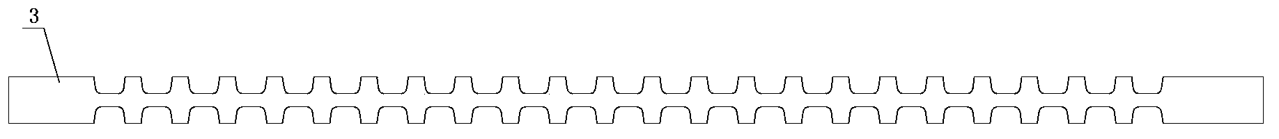
[0037] Such as Figure 5 As shown, an air-cooled integrated bipolar plate for a fuel cell includes a cathode plate 2 and an anode plate 7, two layers of cooling fins 3 are arranged between the cathode plate 2 and the anode plate 7, and two layers of cooling fins 3 There is a fluid channel 5 on it. The fluid channel 5 is stamped from an aluminum alloy plate, that is, parallel grooves with a trapezoidal cross-section are stamped on both sides of the aluminum alloy plate. Such as figure 2 shown. A fuel fluid channel 4 is provided on the cathode plate 2 , and an oxidant fluid channel 8 is provided on the anode plate 7 .
[0038] The cathode plate 2, the two-layer heat sink 3 and the anode plate 7 are integrally formed by injection molding to form a bipolar plate, and the two ends of the bipolar plate are provided with a fuel inlet and outlet main flow channel and an oxidant inlet and outlet main flow channel, such as Figure 5 The shown fuel enters the main flow channel 1 and...
Embodiment 3
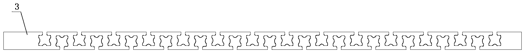
[0041] Such as Figure 6 As shown, an air-cooled integrated bipolar plate for a fuel cell includes a cathode plate and an anode plate, and three layers of heat sinks are arranged between the cathode plate and the anode plate: heat sink a3-1, heat sink b3-2 , heat sink c3-2, fluid passages are provided on the two-layer heat sink. The fluid channel is stamped from the aluminum alloy plate, that is, the upper and lower parallel grooves with a trapezoidal cross-section are stamped on both sides of the aluminum alloy plate, and the heat sink a3-1, heat sink b3-2, and heat sink c3-2 are stacked up and down. Set between the cathode plate and the anode plate.
[0042] The cathode plate, heat sink a3-1, heat sink b3-2, heat sink c3-2 and the anode plate are bonded together by an adhesive to form a bipolar plate, and the cathode plate and the anode of the upper and lower adjacent bipolar plates Membrane electrodes are interposed between the plates to form a single cell, and multiple g...
PUM
 Abstract
Description
Claims
Application Information