A Low-Cost On-Chip Oscillator

An oscillator and low-cost technology, applied in the field of on-chip oscillators, can solve the problems of prolonging chip design and development time, multi-layout area, occupation, etc., and achieve the effect of shortening design and development time, saving chip area and reducing manufacturing cost

Active Publication Date: 2016-08-17
XI AN UNIIC SEMICON CO LTD
View PDF4 Cites 0 Cited by
  • Summary
  • Abstract
  • Description
  • Claims
  • Application Information

AI Technical Summary

Problems solved by technology

In order to reduce the current consumption of the oscillator, it is generally necessary to use larger resistance values ​​of R1 and R2, resulting in further occupying more layout area and increasing the cost of the chip
[0016] (3) The factor ln[(R1+R2) / R1] is a nonlinear function. If you want to adjust the oscillation period linearly through it, it will bring certain difficulties to the calculation and design, and also prolong the design and development time of the chip.

Method used


Image

  • A Low-Cost On-Chip Oscillator
  • A Low-Cost On-Chip Oscillator
  • A Low-Cost On-Chip Oscillator

Examples


Embodiment Construction

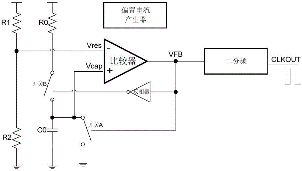
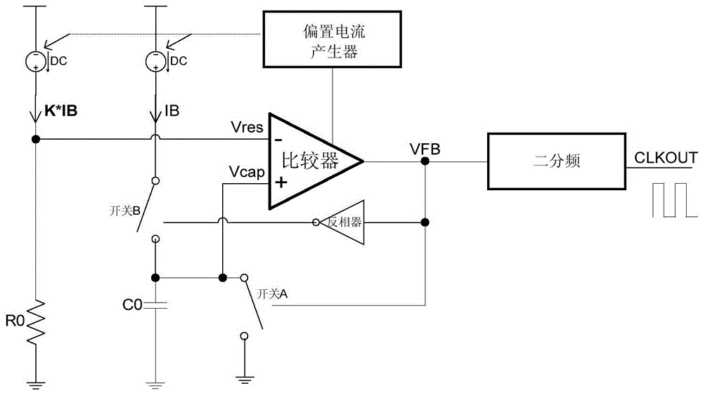
[0032] see image 3 , 4 The schematic diagram and waveform diagram of the shown inventive scheme:

[0033] Among them: the bias current K*IB flows through the resistor R0 to provide a reference voltage for the comparator; the bias current IB and the capacitor C0 form a charging path; the control terminal of switch A is connected to the output terminal of the comparator, and the control terminal of switch B is reversed The phase device is connected to the output terminal of the comparator so that switch A and switch B work in opposite phases. The bias current generator not only provides the comparator with the bias current required for its operation, but also provides the bias currents K*IB and IB; the frequency division circuit divides the frequency of the pulse signal to obtain a clock signal with a duty cycle of 50% .

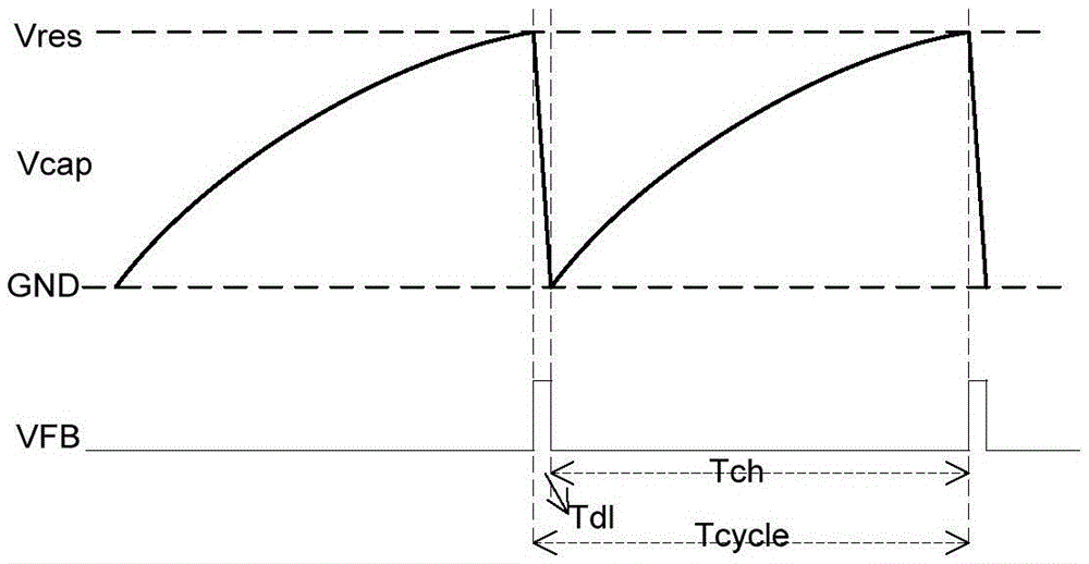
[0034] 1> Clock cycle Tcycle=Tch+Tdl; where Tch: capacitor charging time; Tdl: feedback delay discharge time

[0035] When Tdl<


PUM


Abstract

The invention provides a novel on-chip oscillator circuit structure which can save the chip area and lower chip manufacturing and design cost to a large extent. An on-chip oscillator comprises a comparator, a bias current generator, a reference voltage generating circuit and a charging closed circuit. Bias currents provided by the bias current generator are respectively connected into the reference voltage generating circuit and the charging closed circuit, a bias current source K*IB is formed in the reference voltage generating circuit, and a bias current source IB is formed in the charging closed circuit. The bias current source K*IB in the reference voltage generating circuit and a resistor R0 are connected in series and are grounded, and a voltage dividing node is located between the bias current source K*IB and the resistor R0. The on-chip oscillator has the advantages in a traditional scheme, and can save the chip area and lower chip manufacturing cost to a large extent; for engineering personnel, the difficulty for cyclic calculation and circuit design is lowered, and the design and development time of chips is shortened.

Description

technical field [0001] The invention relates to an on-chip oscillator. Background technique [0002] After the enable signal arrives, the oscillator oscillates internally, generates and outputs a clock signal of a certain frequency, and provides it to the digital system or other digital modules to make it work in an orderly manner. The oscillator can be integrated on the same silicon chip with other circuit blocks to form an on-chip oscillator. [0003] see figure 1 , 2 The schematic diagram and waveform diagram of the traditional scheme shown. Among them: resistors R1 and R2 are divided in series to provide a reference voltage for the comparator; resistor R0 and capacitor C0 form an RC charging path; switch A and switch B work in opposite phases; the bias current generator provides the comparator with its working conditions The required bias current; the two frequency division circuit divides the frequency of the pulse signal to obtain a clock signal with a duty cycle o...

Claims


Application Information

Patent Timeline
Patent Type & Authority Patents(China)
IPC IPC(8): H03H3/04
Inventor 谢永宜俞冰
Owner XI AN UNIIC SEMICON CO LTD
Why Eureka
Try Eureka