Method for preparing polydimethylsiloxane (PDMS) micro-fluidic chip

A microfluidic chip, glass microtechnology, applied in chemical instruments and methods, laboratory utensils, laboratory containers, etc., can solve the problems of high equipment requirements, complex preparation process, high cost, etc., and achieve low cost. Effect

Inactive Publication Date: 2014-07-16
NANJING UNIV OF SCI & TECH
View PDF7 Cites 19 Cited by
  • Summary
  • Abstract
  • Description
  • Claims
  • Application Information

AI Technical Summary

Problems solved by technology

[0005] In view of the disadvantages of the existing microfluidic chip preparation method described above, such as complex preparation process, high equipment requirements, and high cost, the purpose of the present invention is to provide a simple and high aspect ratio PDMS microfluidic chip preparation method

Method used


Image

  • Method for preparing polydimethylsiloxane (PDMS) micro-fluidic chip
  • Method for preparing polydimethylsiloxane (PDMS) micro-fluidic chip

Examples


Embodiment 1

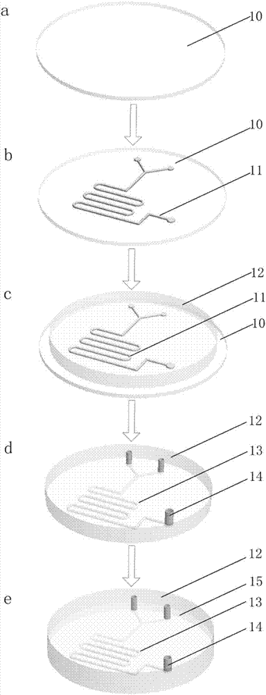
[0029] The preparation of the paraffin positive model 11 of the PDMS microfluidic chip, the specific steps are as follows:

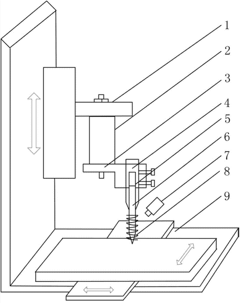
[0030] Step 1 Preparation of the internally structured biconical glass micronozzle 5 : the internally structured biconically shaped glass micronozzle 5 was prepared by adopting the above method for preparing the internally structured biconically shaped glass micronozzle with an outlet diameter of 120 μm.

[0031] Step 2 Cleaning of the glass substrate 10: Put the glass piece into a beaker, pour in an appropriate amount of concentrated sulfuric acid, heat it on a heating furnace for 10 minutes, then take it out and cool it for 10 minutes, and rinse the remaining concentrated sulfuric acid with deionized water. Dry it with a cotton ball, put it into a beaker containing acetone, put it into an ultrasonic cleaner and shake it for 10 minutes, take it out, rinse it with deionized water, and blow dry the surface moisture with nitrogen.

[0032] In step 3, the s...

Embodiment 2

[0035] The preparation of the paraffin positive model 11 of the PDMS microfluidic chip, the specific steps are as follows:

[0036] Step 1 Preparation of the internally structured biconical glass micronozzle 5 : the internally structured biconically shaped glass micronozzle 5 was prepared with the internally structured biconically shaped glass micronozzle having an outlet inner diameter of 180 μm.

[0037] Steps 2 and 3 are identical to steps 2 and 3 described in Example 1

[0038] Step 4 Step 4 Set the driving voltage amplitude of the piezoelectric actuator 2 to 60V, the driving frequency to 2Hz, set the motion parameters of the three-dimensional workbench 9 so that the droplet overlap is 60%, the Z-axis deposition times are 2, and the workbench moves Pattern selection for dual-way micro-mixing patterns for microfluidic chips. Drive the internal double-conical glass micro-nozzle 3, and at this time, the internal double-conical glass micro-nozzle 5 is surrounded by a heating ...

Embodiment 3

[0040] The preparation of the paraffin positive model 11 of the PDMS microfluidic chip, the specific steps are as follows:

[0041] Step 1 Preparation of the internally structured biconical glass micronozzle 5 : the internally structured biconically shaped glass micronozzle 5 was prepared by adopting the above described method for preparing the internally structured biconically shaped glass micronozzle.

[0042] Steps 2 and 3 are identical to steps 2 and 3 described in Example 1

[0043] Step 4 Set the driving voltage amplitude of the piezoelectric actuator 2 to 80V, the driving frequency to 2Hz, set the motion parameters of the three-dimensional table 9 so that the droplet overlap is 80%, the Z-axis deposition times are 6, and the motion pattern of the table is selected Two-way micro-mixing patterns on a microfluidic chip. Drive the internal double-conical glass micro-nozzle 5, and at this moment, the internal double-conical glass micro-nozzle 5 is surrounded by a heating ri...


PUM


Abstract

The invention discloses a method for preparing a polydimethylsiloxane (PDMS) micro-fluidic chip. The method comprises the following steps: preparing a paraffin male die of the PDMS micro-fluidic chip by a droplet micro-injection method; preparing a female die of the PDMS micro-fluidic chip by a molding method; and bonding the female die of the PDMS micro-fluidic chip and a glass substrate together by a reversible bonding mode, thereby preparing the PDMS micro-fluidic chip. The process of preparing the paraffin male die of the PDMS micro-fluidic chip is completed in one step, the cost is low, a specific template is not needed, and a paraffin male die of a PDMS micro-fluidic chip of any graph can be prepared.

Description

technical field [0001] The invention relates to a method for preparing a microfluidic chip, in particular to a method for preparing a PDMS microfluidic chip. Background technique [0002] A microfluidic chip refers to a chemical or biological laboratory built on a chip of a few square centimeters. It integrates the basic operation units involved in chemistry or biology, such as sample preparation, reaction, separation, detection, cell culture, sorting, lysis, etc., into a small chip, forming a network of micro-channels, with controllable fluid running through it. The whole system is used to realize various functions of conventional chemical or biological laboratory. [0003] The materials commonly used to make microfluidic chips include single crystal silicon wafers, glass, quartz and various organic polymers. Silicon has good chemical inertness and thermal stability, but the disadvantages of silicon materials are that they are fragile and expensive , opacity, poor electri...

Claims


Application Information

Patent Timeline
Patent Type & Authority Applications(China)
IPC IPC(8): B01L3/00
Inventor 侯丽雅李宗安朱晓阳朱丽章维一
Owner NANJING UNIV OF SCI & TECH
Why Eureka
Try Eureka