
Large steel bridge deck and manufacture method thereof

A technology for steel bridge decks and steel bridge decks, applied in bridges, manufacturing tools, bridge parts, etc., can solve the problems of bridge deck damage, lateral shrinkage and angular deformation, and the amount of welding filling is not fixed, so as to reduce labor intensity, Ensure welding quality and save welding materials

Active Publication Date: 2014-07-16
CHINA RAILWAY BAOJI BRIDGE GRP
View PDF5 Cites 7 Cited by
  • Summary
  • Abstract
  • Description
  • Claims
  • Application Information

AI Technical Summary

Problems solved by technology

Its disadvantages: First, because there is a gap reserved for the V-shaped groove on one side, the welding filling amount is not fixed, and its lateral shrinkage and angular deformation are relatively large. There is a large amount of damage to the bridge deck, and there is a large amount of repair welding and grinding after welding, and the welding of the interlocking section of the diaphragm is operated in the supine position; second, the single-sided welding and double-sided forming technology requires groove processing and welder operation skills Higher, the overall production efficiency is low, ceramic backing, gas shielded welding wire, submerged arc welding wire, submerged arc flux, shielding gas and other materials are used in welding, and there are many types of materials and high cost

Method used


Image

  • Large steel bridge deck and manufacture method thereof
  • Large steel bridge deck and manufacture method thereof
  • Large steel bridge deck and manufacture method thereof

Examples


Embodiment 1

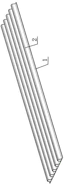
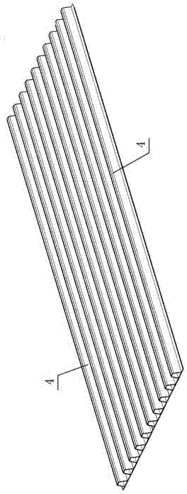
[0015] Embodiment 1: with reference to attached figure 1 ~ attached Figure 4 and Figure 7 . A large steel bridge deck, the steel bridge deck is welded by multiple steel bridge deck blocks, the steel bridge deck block is welded by two or more steel bridge deck units (1+2), the steel bridge deck unit (1 +2) It is composed of several U-shaped ribs 2 and panel 1, several U-shaped ribs 2 are welded on the panel 1 at equal intervals, and the diaphragm connecting plate 3 is welded with U-shaped ribs 2 and panel 1. The shape of the U-shaped rib 2 is a trapezoidal U-shaped rib.

Embodiment 2

[0016] Example 2: On the basis of Example 1, a large-scale steel bridge deck forming method, the prepared steel bridge deck unit (1+2) is laid on the wide tire frame, and the joints are adjusted to be even Positioning welding, using the submerged arc automatic welding process to weld the weld seam on one side of the seam, connecting 2 to 4 steel bridge deck units (1+2) at a time, and then assembling the transverse diaphragm plate 3 according to the position, using the MAG welding process to weld the transverse Partition plate 3 is welded with panel 1 and U-shaped rib 2, and then large-scale lifting equipment is used to turn the plate over 180°, and then the seam 5 between the plate units is welded by submerged arc automatic welding process on the front to form a large plate. During the welding process, design a reasonable groove form (I-type or Y-type groove) at the joint, set a reasonable amount of anti-deformation (0°~2°) to ensure that the flatness meets the requirements; a...


PUM


Abstract

The invention relates to a large steel bridge deck and a manufacture method thereof. The large steel bridge deck is made by welding a plurality of steel bridge deck blocks. Each steel bridge deck block is made by welding two or more steel bridge deck units. Each steel bridge deck unit is composed of a plurality of U-shaped ribs and a face plate; the U-shaped ribs are welded on the face plate at equal intervals; a transverse partition joint plate is welded to the U-shaped ribs and the face plate. The large steel bridge deck has the advantages that operation is simple, and the single-side welding double-side forming technique with high requirements on operating skill is avoided; welding materials are saved, expensive waterproof ceramic pads are not used, and gas shielded welding wires and protective gases are not used; no rigid jig plate is used, steel is saved, damage of the face plates by the jig plates is avoided, and great amount of work such as dismantling the jig plates and repairing is decreased.

Description

technical field [0001] The invention relates to a large-scale steel bridge deck that can connect 2 to 4 plate units with a width of one time to form a large plate to participate in the assembly of steel bridge decks and a manufacturing method thereof, belonging to the field of steel bridge manufacturing. Background technique [0002] Existing highway steel box girders and railway steel bridge integral bridge decks are composed of a huge deck, longitudinal U-shaped ribs and diaphragm connecting plates, and the three are perpendicular to each other to form an orthotropic bridge deck. steel bridge deck structure. The width of the large-scale steel girder bridge deck is 30-40m, and the bridge deck is subdivided into multiple plate units during manufacture, and then the plate units are welded together on the general tire frame. Due to the limitation of the width and length of the steel plate supply, at present, all steel bridge manufacturers use U-shaped ribs 2 and diaphragm con...

Claims


Application Information

Patent Timeline
IPC IPC(8): B23K9/18E01D19/12
CPCB23K9/18E01D19/125E01D2101/30
Inventor 张剑峰吉敏廷李军平朱新华孙立雄王秀菊孙建都
Owner CHINA RAILWAY BAOJI BRIDGE GRP
Learn More