Three-dimensional (3D) printing method and 3D printing system

A 3D printing and printing head technology, applied in the field of 3D printing systems, can solve problems such as long time intervals and the influence of interlayer bonding force, and achieve the effects of shortening printing intervals, enhancing interlayer bonding force, and flexible control

Active Publication Date: 2014-07-16
SHANGHAI REALFAST DIGITAL TECH CO LTD
View PDF2 Cites 43 Cited by
  • Summary
  • Abstract
  • Description
  • Claims
  • Application Information

AI Technical Summary

Problems solved by technology

This method is helpful to increase the printing speed, but it is still a flat layer-by-layer forming method in essence, which cannot solve the p...

Method used


Image

  • Three-dimensional (3D) printing method and 3D printing system
  • Three-dimensional (3D) printing method and 3D printing system
  • Three-dimensional (3D) printing method and 3D printing system

Examples


Embodiment 1

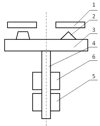
[0036] Embodiment one: see figure 2 As shown, a 3D printing system includes a circular printing platform 3, and the circular printing platform 3 is fixedly connected with a central support rod 4, and is provided with a rotary drive mechanism 5 and a lifting drive mechanism 6, and the rotary drive mechanism 5 The central support rod 4 is driven and connected, so that the circular printing platform 3 rotates around the rotation axis of the center of the circle, and the lifting drive mechanism 6 is driven and connected with the central support rod 4, so that the circular printing platform is raised and lowered in a direction parallel to the rotation axis ; A synchronous control mechanism is provided to connect and control the rotation drive mechanism 5 and the lifting drive mechanism 6 .

[0037] In this embodiment, the rotary drive mechanism 5 can be realized by any existing technology, for example, gear drive, synchronous belt drive, motor shaft direct drive, etc. In order to ...

Embodiment 2

[0041] Embodiment two: see Figure 4 As shown, a 3D printing system has the same basic structure as that of Embodiment 1. In this embodiment, the rotation drive mechanism 5 and the lift drive mechanism 6 are integrated and realized by a set of drive mechanisms.

Embodiment 3

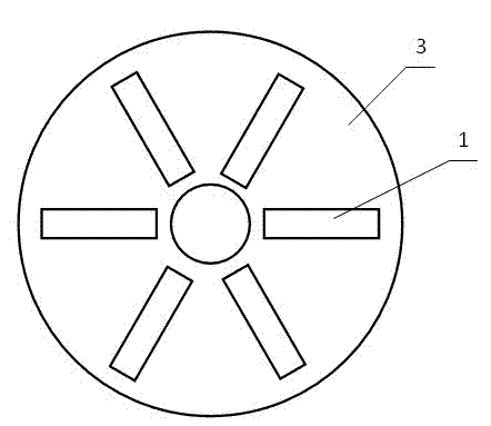
[0042] Embodiment three: see Figure 5 As shown, a 3D printing system, the basic structure is the same as that of Embodiment 1, the difference is that the circular printing platform is fixedly connected with a central support rod 4, and the rotation drive mechanism 5 drives and connects the central support rod 4; A rotary sliding mechanism 7 is slidably connected to the bottom of the circular printing platform, and the lifting drive mechanism 6 drives the circular printing platform 3 to lift through the rotary sliding mechanism 7 .


PUM


Abstract

The invention discloses a three-dimensional (3D) printing method and a 3D printing system. Printing data information of an object is acquired, a printing material is controlled to be molded layer by layer according to the printing data information, and printing is realized. The 3D printing method is characterized by comprising the following steps: providing a circular printing platform for bearing a printing object; setting multiple printing heads on the circular printing platform, wherein multiple nozzles which are radially arranged along the circle are arranged on each printing head; and setting a synchronous control mechanism, and synchronously controlling the circular printing platform to rotate around a rotating shaft in the center of a circle and decline during printing, so that the molded printing layers form a spiral shape on the whole circular printing platform, and the position and shapes of slicing data of the printing data information in the object are consistent with the spiral layer shape of the printing object. Multi-layer synchronous printing in a printing period is realized, the printing speed is improved, and the interlayer binding force is enhanced.

Description

technical field [0001] The invention relates to a 3D physical printing molding technology, in particular to a 3D printing method for realizing rapid printing, and a corresponding 3D printing system. Background technique [0002] 3D printing technology is a rapid prototyping technology, which is based on digital model files, using powdered metal, plastic resin and other materials, using methods such as adhesive bonding and light curing, to construct objects by layer-by-layer printing. Among them, several commonly used printing methods are: through the print head to spray adhesive bonding molding to the laid powder material layer; for photocuring resin using UV light irradiation photocuring molding; for metal powder laser sintering; for thermoplastic powder Laser sintering or thermal sintering etc. [0003] These methods usually need to use a print head to print layer by layer. First, use computer modeling software to model, and then slice the generated 3D model to generate ...

Claims


Application Information

Patent Timeline
IPC IPC(8): B29C67/00B22F3/105
Inventor 谢红军洪叶
Owner SHANGHAI REALFAST DIGITAL TECH CO LTD
Why Eureka
Try Eureka