Loading machine tire retreading structure
A tire retreading and loader technology, which is applied in the field of grinding tooling, can solve the problems of weakening the protective effect of the tire tread on the carcass, piercing and blasting of the tire ply, and the reduction of the impact resistance of the elastic domain, so as to reduce the tire Surface unevenness, convenient and timely adjustment, and the effect of preventing deformation
- Summary
- Abstract
- Description
- Claims
- Application Information
AI Technical Summary
Problems solved by technology
Method used
Image
Examples
Embodiment 1
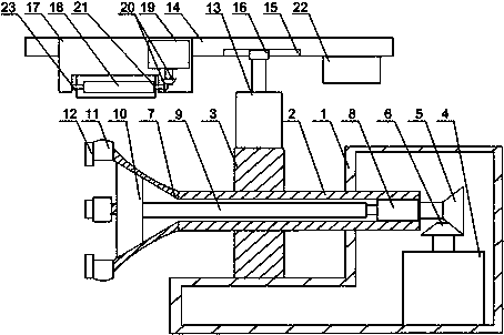
[0023] Such as Figure 1 to Figure 2As shown, a loader tire retreading structure of the present invention includes an L-shaped support base 1, a sleeve 2, a column 3 and a DC motor 4 are arranged on the L-shaped support base 1, the sleeve 2 passes through the column 3, A large gear 5 is installed on one end of the sleeve 2, a pinion 6 is installed on the output end of the DC motor 4, the large gear 5 cooperates with the pinion 6, and an expansion clamping part is installed on the other end of the sleeve 2, A first air cylinder 8 is arranged inside the sleeve 2, the output end of the first air cylinder 8 is connected with a connecting rod 9, the end of the connecting rod 9 is equipped with a slider 10 matched with the expansion clamping part, and a second air cylinder is also included 13 and a support rod 14, the support rod 14 is provided with a trapezoidal groove 15, the output end of the second cylinder 13 is provided with a protrusion 16, and the protrusion 16 is engaged wi...
Embodiment 2
[0026] Such as Figure 1 to Figure 2 As shown, this embodiment is based on Embodiment 1, the expansion clamping part includes an elastic expansion cover 7, the small diameter end of the elastic expansion cover 7 is connected to the sleeve 2, and the elastic expansion cover 7 A claw 11 is installed on the large diameter end, and the upper end surface of the claw 11 is arc-shaped. When clamping the tire, the elastic expansion cover 7 passes through the inner side of the bead, and the claws 11 are in contact with the inner wall of the bead. stability, and when the sleeve 2 rotates, it avoids slipping between the inner wall of the bead and the claw 11, and further reduces the unevenness when cutting the tread.
Embodiment 3
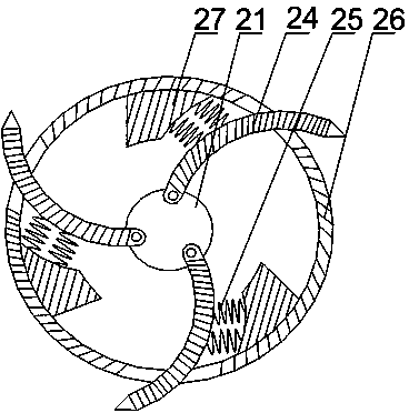
[0028] Such as figure 2 As shown, on the basis of Embodiment 1, the present embodiment includes a cylindrical body 26 and a rotating shaft 21, the rotating shaft 21 is arranged in the cylindrical body 26, the two ends of the rotating shaft 21 protrude from the two ends of the cylindrical body 26, and the rotating shaft 21 One end is rotatably connected to the tool holder 17, the other end of the rotating shaft 21 is connected to the bevel gear 20, and a plurality of arc-shaped blades 24 are uniformly arranged on the rotating shaft 21, and the arc-shaped blades 24 are hinged to the rotating shaft 21. 26 is provided with an opening corresponding to the arc-shaped blade 24, and the arc-shaped blade 24 runs through the opening. A block 27 is arranged on the inner wall of the cylinder 26. One side of the block 27 is an arc-shaped concave surface, and the arc-shaped concave surface and the arc-shaped The arc outer sides of the blades 24 are connected by a spring 25 . Rotating shaf...
PUM
 Abstract
Description
Claims
Application Information
 - R&D
- Intellectual Property
- Life Sciences
- Materials
- Tech Scout
- Unparalleled Data Quality
- Higher Quality Content
- 60% Fewer Hallucinations
Browse by: Latest US Patents, China's latest patents, Technical Efficacy Thesaurus, Application Domain, Technology Topic, Popular Technical Reports.
© 2025 PatSnap. All rights reserved.Legal|Privacy policy|Modern Slavery Act Transparency Statement|Sitemap|About US| Contact US: help@patsnap.com


