A uniform electrochemical treatment method for the inner surface of a tubular workpiece

A processing method and electrochemical technology, applied in the field of electrochemistry, can solve the problems of inability to prepare a coating with uniform thickness or uniform electrochemical treatment, so as to achieve good uniformity and improve the effect of uniformity

Inactive Publication Date: 2016-06-15
SICHUAN INST OF MATERIALS & TECH
View PDF8 Cites 0 Cited by
  • Summary
  • Abstract
  • Description
  • Claims
  • Application Information

AI Technical Summary

Problems solved by technology

[0005] The purpose of the present invention is to provide a uniform electrochemical treatment method for the inner surface of the tubular workpiece in view of the common problem that it is impossible to prepare a uniform thickness coating or uniform electrochemical treatment when electrochemically treating the inner surface of the tubular workpiece

Method used


Image

  • A uniform electrochemical treatment method for the inner surface of a tubular workpiece
  • A uniform electrochemical treatment method for the inner surface of a tubular workpiece
  • A uniform electrochemical treatment method for the inner surface of a tubular workpiece

Examples


Embodiment 1

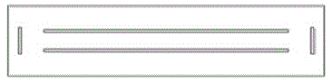
[0065] Such as figure 1 As shown, the copper anodes are placed at the mouths of both ends of the pipeline, and the parameters are set according to Table 1 for simulation calculation.

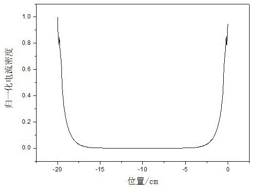
[0066] figure 1 It is the calculation model figure of embodiment 1, figure 2 It is the current density distribution figure of embodiment 1, image 3 It is the normalized current density distribution diagram obtained by simulation calculation in Example 1. figure 1 In the middle, the middle part is a pipe, and the two sides are copper anodes.

[0067] As can be seen from the calculation results of Example 1, the electroplating anode is placed at the two ports of the pipeline, and the current density distribution is mainly concentrated at the mouth of the pipeline. The farther the distance from the mouth is, the smaller the current density is. The current density on the inner surface tends to zero. The normalized current density distribution is between 0 and 1. The normalized current density...

Embodiment 2

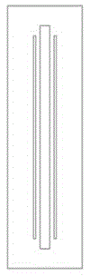
[0069] A copper rod with a length of 22cm and a diameter of 10mm is inserted into the pipeline as an anode, and the simulation calculation is carried out according to the set parameters.

[0070] Figure 4 It is the calculation model figure of embodiment 2, Figure 5 It is the current density distribution figure of embodiment 2, Figure 6 It is the normalized current density distribution diagram obtained by simulation calculation in Example 2.

[0071] From the calculation results of Example 2, it can be seen that after the electroplating anode is inserted into the pipeline, the current density distribution on the inner surface of the pipeline is significantly improved compared with Example 1, but the current density at the mouth of the electroplating pipeline is still quite different from that in the middle of the pipeline. When the current density is distributed between 0.63 and 1, the uniformity of the coating thickness distribution is still poor.

Embodiment 3

[0073] A copper rod with a length of 2cm and a diameter of 10mm is inserted into the pipe as an anode, and is scanned and moved up and down along the axis of the target pipe at a constant speed at a constant speed, and the simulation calculation is carried out according to the set parameters.

[0074] Figure 7 It is the calculation model figure of embodiment 3, Figure 8 It is the current density distribution figure of embodiment 3, Figure 9 It is the normalized current density distribution diagram obtained by simulation calculation in Example 3.

[0075] From the calculation results of Example 3, it can be seen that during the uniform scanning motion of the anode reciprocating up and down along the axis in the pipeline, the instantaneous current density distribution in the pipeline changes with the change of the position of the anode, although the instantaneous current density distribution on the inner surface of the pipeline is not uniform , but after the superposition o...


PUM


Abstract

The invention discloses a homogeneous electrochemical treatment method of an inner surface of a tubular workpiece, aiming at solving the general problem that a uniform-thickness coating can not be prepared or homogeneous electrochemical treatment can not be carried out when the inner surface of the tubular workpiece is subjected to electrochemical treatment currently. The method disclosed by the invention comprises the following steps that a counter electrode is inserted into the tubular workpiece, the counter electrode and the tubular workpiece are used as two poles for electrochemical treatment, the counter electrode and the tubular workpiece do relative axial motion along the axis of the tubular workpiece in the process of electrochemical treatment. The method disclosed by the invention can effectively solve the above problem, a coating with good homogeneity can be prepared on the inner surface of the tubular workpiece, and the homogeneity of the coating is improved remarkably; meanwhile, the method disclosed by the invention is simple to operate, low in equipment and low in cost, and can meet industrial production demands; meanwhile, through measures such as control of relative movement speed, arrangement of subsidiary conduit and series connection of multiple counter electrodes, the homogeneity of the coating is further improved, and the preparation requirement of super-long tubular workpiece coating can be met.

Description

technical field [0001] The invention relates to the field of electrochemistry, in particular to a method for surface electrochemical treatment, in particular to a uniform electrochemical treatment method for the inner surface of a tubular workpiece. Background technique [0002] The outer conductor of the high-power input coupler uses the inner wall of a 316L stainless steel tube. The inner wall of the 316L stainless steel tube needs to be plated with a uniform oxygen-free copper coating to meet the need to further improve the power transmission level of the high-power input coupler in the superconducting cavity. For the inner surface of through-holes in metal pipes or parts with an aspect ratio greater than 3, conventional electrochemical treatment methods such as electroplating and electrolysis cannot produce uniform thickness coatings or uniform electrochemical treatment due to uneven current density distribution. , There may even be a problem that there is no coating in ...

Claims


Application Information

Patent Timeline
Patent Type & Authority Patents(China)
IPC IPC(8): C25D5/04C25D7/04
Inventor 王庆富陈林法涛黄煌王晓红
Owner SICHUAN INST OF MATERIALS & TECH
Why Eureka
Try Eureka