Parallel motion high-low-pressure power machine and application thereof

A power machine and parallel motion technology, applied in the field of high and low voltage power equipment, can solve the problems of high manufacturing cost and high cost, and achieve the effect of low manufacturing cost, low noise and simple machine structure

Active Publication Date: 2014-07-16
郭远军
View PDF10 Cites 8 Cited by
  • Summary
  • Abstract
  • Description
  • Claims
  • Application Information

AI Technical Summary

Problems solved by technology

[0012] The invention overcomes the high cost of the expansion chamber, compression chamber, heater, cooling chamber, regenerator, etc. in the Stirling engine, and the heat loss is 2-3 times that of the internal combustion engine; it overcomes the need for an organic Rankine cycle system. Expander or steam turbine, a technical problem with high manufacturing costs

Method used


Image

  • Parallel motion high-low-pressure power machine and application thereof
  • Parallel motion high-low-pressure power machine and application thereof

Examples


Embodiment 1

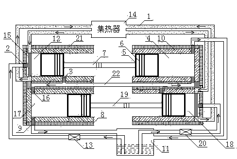
[0029] A parallel motion high and low pressure power machine, comprising a heat preservation pipe 1, an atomizer 2, an exhaust valve 3, a low pressure cylinder I4, a piston 5, a piston ring 6, a push-pull rod I7, a radiator 8, an exhaust check valve 9, Rack 10, liquid storage tank 11, high pressure cylinder I12, pressure valve I13, collector 14, gasification reactor 15, intake check valve 16, low pressure cylinder II17, high pressure cylinder II18, push-pull rod II19, pressure valve II20 and insulation layer 21; both ends of push-pull rod I7 are respectively provided with piston 5, two pistons 5 are respectively provided in high-pressure cylinder I12 and low-pressure cylinder I4, piston ring 6 is provided on piston 5; both ends of push-pull rod II19 are respectively provided with pistons 5, the two pistons 5 are respectively arranged in the high pressure cylinder II18 and the low pressure cylinder II17, and the piston 5 is provided with a piston ring 6; the high pressure cylind...

Embodiment 2

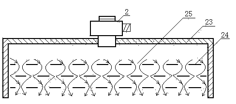
[0031]As mentioned above, the parallel motion high and low pressure power machine, the gasification reactor (15) includes a pressure shell 23, a gasification heat-conducting sheet 24, air holes 25, and an atomizer 2. The gasification and heat-conducting sheet 24 is arranged on the pressure shell 23, and the gas The thermal conductive sheet 24 is provided with air holes 25 in an array, and the air inlet end of the pressure shell 23 is provided with an atomizer 2; the pressure valve I13 and the pressure valve II20 are associated with the push-pull rod I7 and the push-pull rod II19, and the pressure valve is opened and closed once every time a cycle is completed; A transmission shaft is arranged on the push-pull rod, which is connected with the generator rotor to cut the magnetic field lines, so as to form a parallel motion high and low voltage power machine power generation equipment.


PUM


Abstract

The invention relates to a parallel motion high-low-pressure power machine and the application of the parallel motion high-low-pressure power machine. The machine comprises a heat insulation pipe, atomizers, exhaust valves, a low-pressure cylinder I, pistons, piston rings, a push-pull rod I, coolers, exhaust one-way valves, racks, a liquid storage tank, a high-pressure cylinder I, a pressure valve I, a heat collector, gasification reactors, intake one-way valves, a low-pressure cylinder II, a high-pressure cylinder II, a push-pull rod II, a pressure valve II and heat insulation layers. The machine has the advantages that recycling of working media is achieved, and no pollution is produced; the heat energy conversion efficiency ranges from 65% to 98%; the capacity of the air cylinders of the machine can be adjusted according to needed power to adjust output power; liquid filling can be adjusted in the largest power range to adjust the output power; the machine is used for carrying out gasification action on the working media, and knocking does not occur in the whole process; the machine is simple in structure and low in manufacturing cost; the acting power of the machine is two times that of a single cylinder; the machine can avoid the consumption of conventional energy resources, and is high in economic benefit, environmentally friendly and low in noise.

Description

technical field [0001] The invention belongs to the field of high and low pressure power equipment, especially the use of solar energy, geothermal heat, high temperature gas produced by combustion of combustibles, internal combustion engine exhaust gas, high temperature gas discharged from factories and other thermal energy converted into kinetic energy and the temperature of the medium gas in the machine and the heat dissipation outside the machine. It is a power machine that makes the airtight cylinder generate negative pressure to convert thermal energy into kinetic energy. Background technique [0002] Traditional power equipment includes steam engine, internal combustion engine, and external combustion engine. [0003] Steam engine: Inseparable from the boiler, the whole device is cumbersome and bulky; the pressure and temperature of the new steam cannot be too high, the exhaust pressure cannot be too low, and the thermal efficiency is difficult to improve; it is a reci...

Claims


Application Information

Patent Timeline
Patent Type & Authority Applications(China)
IPC IPC(8): F02G1/044F02G1/053
Inventor 郭远军
Owner 郭远军
Why Eureka
Try Eureka