Combined light source and mask optimization method for lithography machine

A technology of joint optimization and lithography machine, applied in the field of lithography machine, can solve problems such as increasing the complexity of optimization methods, difficult to solve analytical expressions, and inability to solve problems

Active Publication Date: 2014-07-16
SHANGHAI INST OF OPTICS & FINE MECHANICS CHINESE ACAD OF SCI
View PDF6 Cites 26 Cited by
  • Summary
  • Abstract
  • Description
  • Claims
  • Application Information

AI Technical Summary

Problems solved by technology

With the continuous improvement of the complexity of the forward lithography imaging model and the evaluation function expression, the analytical expression of the evaluation function gradient is difficult or even impossible to solve, which increases the complexity of the optimization method

Method used


Image

  • Combined light source and mask optimization method for lithography machine
  • Combined light source and mask optimization method for lithography machine
  • Combined light source and mask optimization method for lithography machine

Examples


Embodiment Construction

[0037] The present invention will be further described below in conjunction with embodiment and figure, but should not limit protection scope of the present invention with this embodiment, but for those skilled in the art, under the premise of not departing from the principle of the present invention, can also make some Replacement and improvement, these should also be regarded as belonging to the protection scope of the present invention.

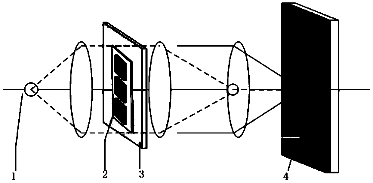
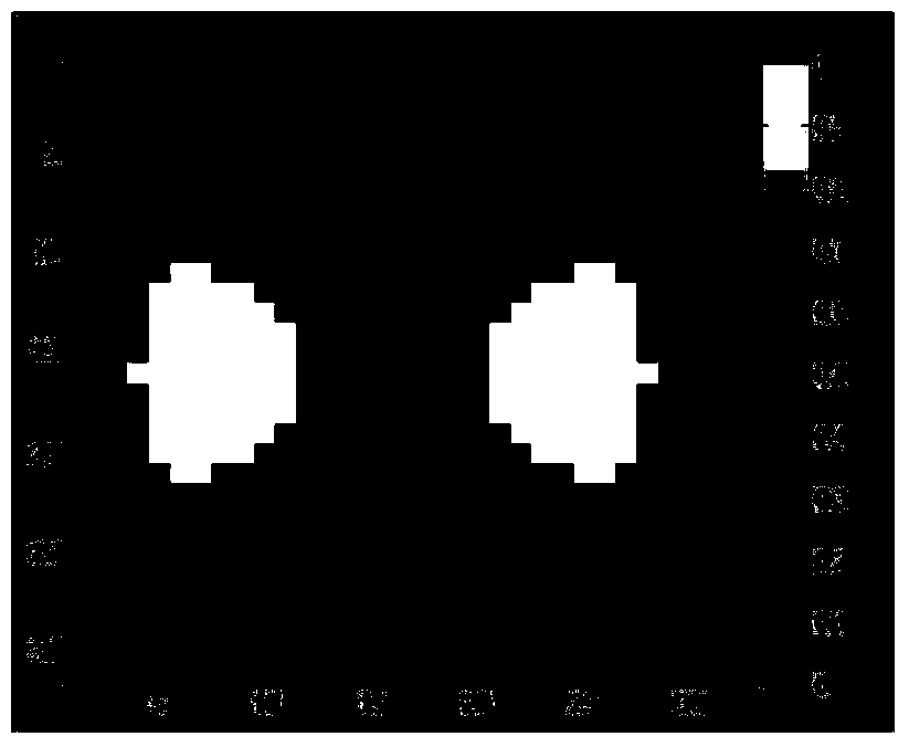
[0038] refer to figure 1 , figure 1 It is a schematic diagram of the lithography machine system of the method for optimizing the light source mask of the lithography machine used in the present invention. It can be seen from the figure that the method involves the light source illumination mode 1 generated by the lithography machine lighting system, the mask pattern 2, and the bearing Mask stage 3 of mask pattern 2, photoresist 4. refer to figure 2 , figure 2It is a schematic diagram of the initial lighting mode of the light source u...


PUM


Abstract

The invention discloses a light source and mask optimization method for a lithography machine. The method comprises the following steps: taking the square of Euclidean distance between an ideal pattern and a photoresist image which corresponds to the mask under exposure of the current light source illumination mode as an evaluation function by utilizing a pixilated light source illumination mode and a mask, calculating gradient information of the evaluation function by utilizing a stochastic parallel gradient descent algorithm, guiding the light source and mask optimization process through the gradient information of the evaluation function, and thus obtaining the optimal light source illumination mode and mask pattern. According to the method, solution of a gradient analysis expression of the evaluation function is avoided, the optimization complexity is reduced, the optimization efficiency is improved, and the resolution ratio of the lithography machine is effectively improved.

Description

technical field [0001] The invention relates to a photolithography machine, in particular to a joint optimization method for a light source and a mask of a photolithography machine. Background technique [0002] Photolithography is one of the core technologies in the manufacture of very large scale integrated circuits. Lithographic resolution determines the feature size of an integrated circuit pattern. When the exposure wavelength and numerical aperture are constant, to continue to improve the lithography resolution, the process factor must be reduced by improving the photoresist process and adopting resolution enhancement technology. Source Mask Optimization (hereinafter referred to as SMO) technology is a new resolution enhancement technology newly developed in recent years, which optimizes the illumination mode of the light source and the mask pattern at the same time. Compared with optical proximity correction technology, it increases the degree of freedom to optimize...

Claims


Application Information

Patent Timeline
Patent Type & Authority Applications(China)
IPC IPC(8): G03F7/20G03F1/76
Inventor 李兆泽李思坤王向朝
Owner SHANGHAI INST OF OPTICS & FINE MECHANICS CHINESE ACAD OF SCI
Why Eureka
Try Eureka