Solar Cell, Module Thereof And Manufacture Method Thereof

A technology of solar cells and manufacturing methods, applied in the direction of final product manufacturing, sustainable manufacturing/processing, circuits, etc., can solve the problems of damage to the structure and function of the back electric field, deterioration of current collection efficiency, deterioration of battery conversion efficiency, etc. Improve the effect of current collection, eliminate end points, and increase the effect of open circuit voltage

Inactive Publication Date: 2014-07-16
MOTECH INDUSTRIES
View PDF6 Cites 3 Cited by
  • Summary
  • Abstract
  • Description
  • Claims
  • Application Information

AI Technical Summary

Problems solved by technology

[0007] The problem of the above-mentioned passivation layer 93 material remaining at the end of the linear opening 94 will affect the contact between the back electrode 95 and the substrate 91, and then make the current collection performance worse, because the back electrode 95 is screen printed. The conductive paste will be disturbed by the residual material of the passivation layer 93, so it is difficult to completely fill the end points of the linear openings 94, which will cause the Al-Si alloy formed by mixing the conductive paste material and the substrate 91 material The thickness of the back electric field structure (BSF) 92 is thinner, and then the thickness of the back electric field structure (BSF) 92 formed by subsequent sintering is thinner and the quality is poor, and thus the function of the back electric field structure 92 is damaged, thereby causing a decrease in the open circuit voltage and short circuit current, and making the The conversion efficiency of the battery deteriorates

Method used


Image

  • Solar Cell, Module Thereof And Manufacture Method Thereof
  • Solar Cell, Module Thereof And Manufacture Method Thereof
  • Solar Cell, Module Thereof And Manufacture Method Thereof

Examples


Embodiment Construction

[0041] The present invention will be described in detail below with reference to the accompanying drawings and embodiments. It should be noted that in the following description, similar elements are denoted by the same numerals.

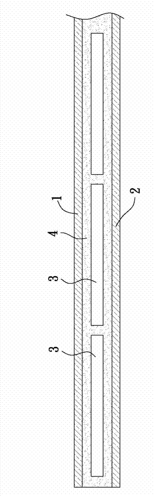
[0042] refer to image 3 , Figure 4 The first preferred embodiment of the solar cell module of the present invention includes: a first plate 1 and a second plate 2 oppositely arranged, and a plurality of arrays arranged between the first plate 1 and the second plate 2 Solar cells 3 , and at least one packaging material 4 located between the first plate 1 and the second plate 2 and in contact with the plurality of solar cells 3 . Wherein, the module can include at least one solar cell 3 , and multiple solar cells 3 are not absolutely necessary.

[0043] The implementation of the first plate 1 and the second plate 2 is not particularly limited, glass or plastic plates can be used, and the plate on the side of the light-receiving surface of the batte...


PUM


Abstract

The present invention provides a solar cell, a module thereof and a manufacture method thereof. The cell comprises a substrate possessing a right side and a back side, an emitter layer arranged on the right side, and a passivation layer arranged on the back side, an opening arranged on the passivation layer in an extension and bending manner, and a backside electrode arranged on the passivation layer and contacted with the back side via the opening. The projection area of the opening on the back side is 3% to 12% of the area of the back side. The present invention also provides another cell which comprises a plurality of annular openings surrounding annularly from inside to outside. By the design of the continuously extending and bending single opening or the plurality of annular openings, the current collection effect of the backside electrode can be enhanced. Moreover, a back electric field structure formed by sintering is enough in thickness and good in quality, thereby improving the photoelectric conversion efficiency of the cell.

Description

technical field [0001] The invention relates to a solar cell, its module and its manufacturing method, in particular to a silicon crystal solar cell, its module and its manufacturing method. Background technique [0002] refer to figure 1 , figure 2 , the known silicon solar cell mainly includes: a substrate 91 with an opposite front surface 911 and a back surface 912, a plurality of back electric field structures (Local Back Surface Field, LBSF for short) 92 located at local parts of the back surface 912, A passivation layer 93 on the back surface 912, a plurality of linear openings 94 on the passivation layer 93, a back electrode 95 on the passivation layer 93, at least one on the passivation layer 93 The bus electrode 96 is in contact with the back electrode 95 and a front electrode 97 is located on the front surface 911 of the substrate 91 . [0003] The passivation layer 93 is used to repair and reduce surface defects of the substrate 91 , thereby reducing the recom...

Claims


Application Information

Patent Timeline
Patent Type & Authority Applications(China)
IPC IPC(8): H01L31/0224H01L31/042H01L31/18
CPCH01L31/022441H01L31/042H01L31/1804Y02E10/547Y02P70/50
Inventor 赖俊文方婷刘浩伟李昆儒
Owner MOTECH INDUSTRIES
Why Eureka
Try Eureka