Relaying protection equipment setting method and device

A relay protection and equipment technology, applied in the direction of emergency protection circuit devices, electrical components, etc., can solve the problems of calculation result error of branching coefficient, influence of safe operation of power grid, short-circuit current and actual data error of upper-level line and lower-level fault line, etc. Achieve the effect of enhancing stability, reducing misoperation and ensuring accuracy

Active Publication Date: 2014-07-16
POWER DISPATCHING CONTROL CENT OF GUANGDONG POWER GRID CO LTD +1
View PDF4 Cites 18 Cited by
  • Summary
  • Abstract
  • Description
  • Claims
  • Application Information

AI Technical Summary

Problems solved by technology

Therefore, when the operation mode of the power supply of the power system changes, the equivalent reactance and other data of the power supply will also change accordingly. Since the data for calculating the branching coefficient in the existing technology comes from the fixed data in the configuration file, it cannot truly reflect the above changes. , so that there is an error between the calculated short-circuit current of the upper-level line and the lower-level fault line and the actual data, that is, there is an error in the calculation result of the branch coefficient, resulting in an inaccurate setting calculation result of the relay protection setting value, thus affecting the action of the protection equipment The situation will also have a certain impact on the safe operation of the entire power grid

Method used


Image

  • Relaying protection equipment setting method and device
  • Relaying protection equipment setting method and device
  • Relaying protection equipment setting method and device

Examples


Embodiment 1

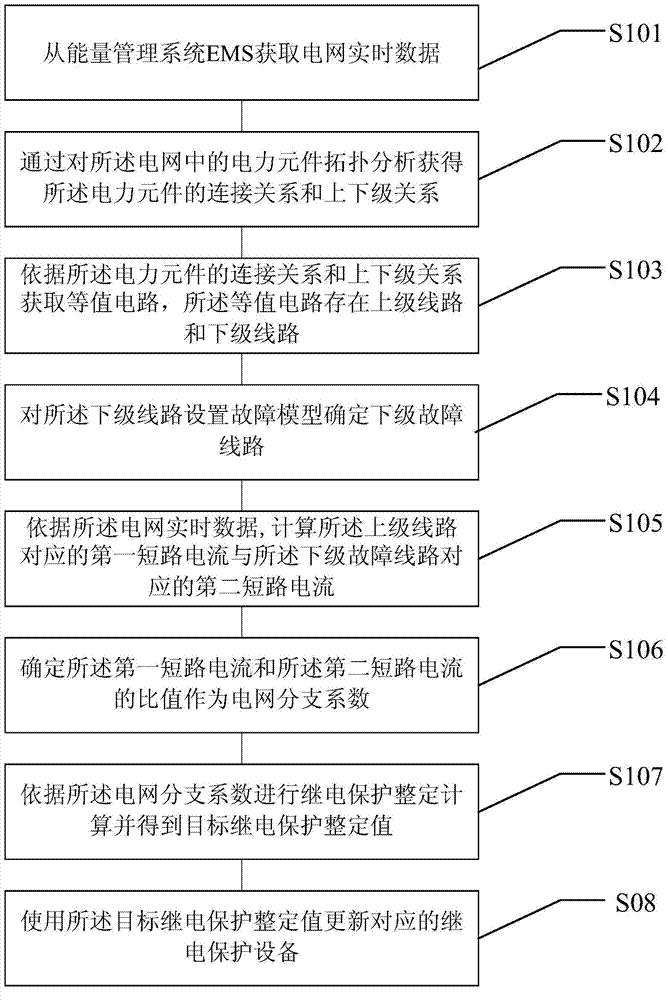
[0036] see Figure 1-a , Figure 1-a A flow chart of a relay protection setting method provided by Embodiment 1 of the present invention is shown, the method includes:

[0037] S101. Obtain real-time data of a power grid from an energy management system EMS.

[0038] The real-time data of the power grid includes data such as the active power of the line in the power grid, the voltage of the busbar, and the equivalent impedance of the power supply;

[0039] Obtaining real-time data of the power grid can be realized through the energy management system EMS (Energy Manage system). The energy management system EMS exports the grid model data by outputting the common information model CIM (Common Information Model) / extensible markup language XML (Extensible Markup Language) file conforming to the IEC61970 standard, and outputs the measurement data and state estimation result data according to the easy language specification. The grid model and real-time measurement data are obtain...

Embodiment 2

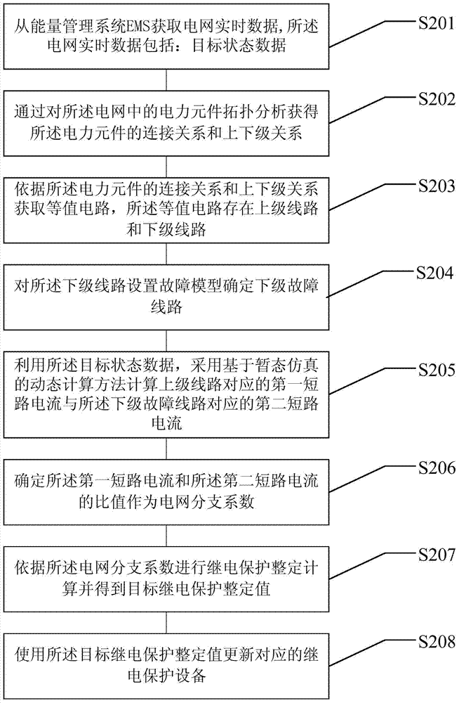
[0067] see figure 2 , figure 2 A flow chart of Embodiment 2 of a relay protection setting method provided by the present invention is shown, and the method specifically includes:

[0068] S201. Acquire real-time grid data from an energy management system EMS, where the real-time grid data includes: target state data.

[0069] The target state data is state estimated data. The so-called state estimation is a method of estimating the internal state of a dynamic system based on available measurement data. The data obtained by measuring the input and output of the system can only reflect the external characteristics of the system, while the dynamic laws of the system need to be described by internal (usually not directly measurable) state variables. Therefore, state estimation is of great significance for understanding and controlling a system. The state estimation data includes the data before the state estimation and the data after the state estimation. The data before the...

Embodiment 3

[0091] see image 3 , image 3 It shows a schematic structural diagram of a relay protection device setting device provided by an embodiment of the present invention, the device includes:

[0092] The grid real-time data acquisition module 310 is used to acquire grid real-time data from the energy management system EMS;

[0093] The power component module 320 is configured to obtain the connection relationship and the superior-subordinate relationship of the power components by analyzing the topology of the power components in the power grid;

[0094] An equivalent circuit acquisition module 330, configured to acquire an equivalent circuit according to the connection relationship and the upper-lower relationship of the power components obtained by the power component module 320, and the equivalent circuit has upper-level lines and lower-level lines;

[0095] A fault model setting module 340, configured to set a fault model for the subordinate line in the equivalent circuit a...


PUM


Abstract

The invention discloses a relaying protection equipment setting method and device. The method comprises the steps of obtaining real-time data of a power grid from an EMS, obtaining the connection relation and the leader-member relation of power elements in the power grid, obtaining a corresponding equivalent circuit, setting a fault model for a subordinate circuit, determining a subordinate fault circuit, calculating the ratio between first short-circuit current corresponding to a superior circuit and second short-circuit current corresponding to the subordinate fault circuit according to the real-time data of the power grid, regarding the ratio as a branch coefficient of the power grid, obtaining a target relaying protection setting value and updating corresponding relaying protection equipment according to the target relaying protection setting value. The branch coefficient is calculated through real-time data of the power grid. The data of the power grid have the real-time performance and are not affected by changes of the operating mode of a power source, so that the accuracy of the relaying protection setting value obtained by calculation of the branch coefficient is ensured, false operations of a protection device are reduced, and the stability of a power grid system is enhanced.

Description

technical field [0001] The invention relates to the technical field of power systems, in particular to a method and device for setting relay protection equipment in a power system. Background technique [0002] Relay protection is the use of relay protection devices to protect the power system and its components (generators, transformers, transmission lines, etc.) In the shortest time and in the smallest area, the faulty equipment is automatically removed from the system, or a signal is sent to the technician to eliminate the root cause of the abnormal working condition, so as to reduce or avoid the damage of the equipment and the impact on the power supply of the adjacent area. [0003] In order to reduce the scope of fault elimination, relay protection should be selective. Specifically, when a short circuit occurs in a device or line in the power system, its relay protection only cuts off the faulty device or line from the power system. When the protection of the faulty e...

Claims


Application Information

Patent Timeline
Patent Type & Authority Applications(China)
IPC IPC(8): H02H7/26
Inventor 曾耿晖毕兆东李剑辉夏彦辉黄明辉俞秋阳邱建方胜文李一泉郑杨斌
Owner POWER DISPATCHING CONTROL CENT OF GUANGDONG POWER GRID CO LTD
Why Eureka
Try Eureka