
Concentrating photovoltaic-photo-thermal-wind power-thermoelectricity integrated system

A concentrating photovoltaic and photovoltaic power generation technology, applied in the field of comprehensive utilization of solar energy, can solve problems such as limited collector area and negative effects of collectors, and achieve the effect of improving the utilization rate of natural energy

Active Publication Date: 2014-07-16
ANHUI UNIVERSITY OF TECHNOLOGY
View PDF10 Cites 7 Cited by
  • Summary
  • Abstract
  • Description
  • Claims
  • Application Information

AI Technical Summary

Problems solved by technology

This application uses the temperature difference between the battery back plate and the heat collector tube to further generate electricity while utilizing photovoltaic light and heat, which improves the efficiency of solar energy utilization to a certain extent, but its disadvantages are: (1) The area of ​​the heat collector is limited , only a small amount of solar energy can be received, and there is still room for further improvement in the utilization of solar energy efficiency; (2), although the heat collector can transfer heat to the water flow, heating water and cooling effect at the same time, but because the heat collector is sealed The excess heat will still have a negative effect on the collector; (3), only using photovoltaic power generation, can still further use the natural wind power to generate power, further improve the utilization rate of natural energy, and better meet the needs of users for heat need

Method used


Image

  • Concentrating photovoltaic-photo-thermal-wind power-thermoelectricity integrated system
  • Concentrating photovoltaic-photo-thermal-wind power-thermoelectricity integrated system
  • Concentrating photovoltaic-photo-thermal-wind power-thermoelectricity integrated system

Examples


Embodiment 1

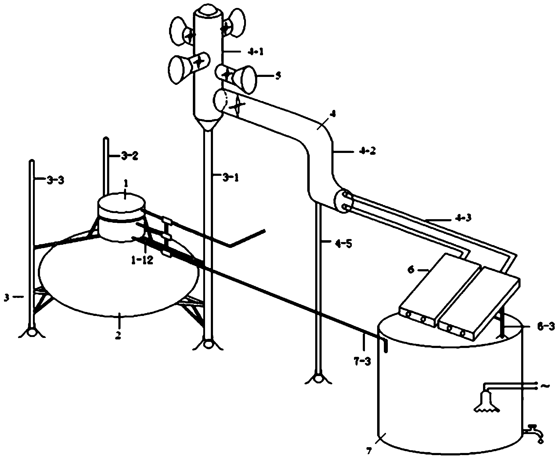
[0052] In conjunction with the accompanying drawings, a concentrating photovoltaic-photothermal-wind power-thermoelectric integrated system in this embodiment includes a photovoltaic photothermal temperature difference power generation boiler 1, a concentrating solar cooker 2, a solar cooker and a boiler support 3, and a ventilation duct 4 , wind power generation device 5, solar cell assembly 6 and heat preservation water storehouse 7 (as figure 1 shown).

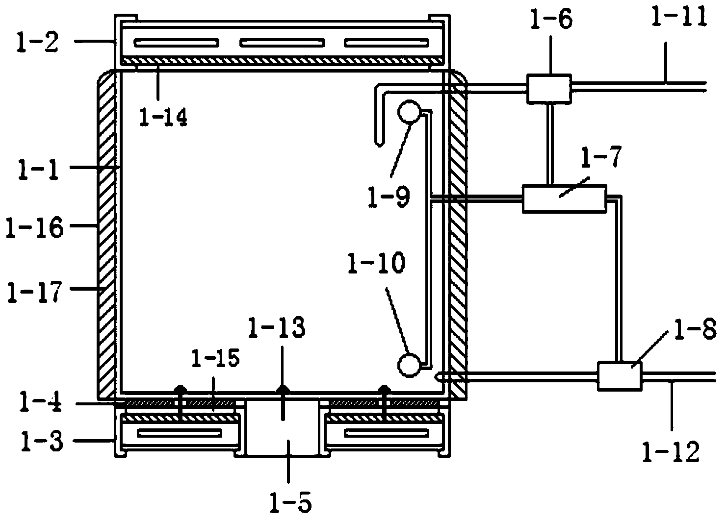
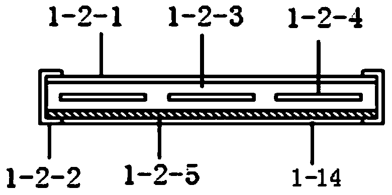
[0053] The photovoltaic photothermal thermoelectric power generation boiler 1 in this embodiment includes a furnace body 1-1, a top photovoltaic power generation module 1-2, a waterproof board 1-14, a bottom photovoltaic power generation heat collector 1-3, a heat transfer plate 1-15, Thermoelectric power generation sheet 1-4, heat transfer alloy block 1-5, upper solenoid valve 1-6, temperature control and water control device 1-7, lower solenoid valve 1-8, upper water level sensor 1-9, lower water level sensor and Tempera...


PUM

PropertyMeasurementUnit
Diameteraaaaaaaaaa

Abstract

The invention discloses a concentrating photovoltaic-photo-thermal-wind power-thermoelectricity integrated system and belongs to the technical field of solar comprehensive utilization. The integrated system comprises a photovoltaic photo-thermal temperature difference power generation boiler, a concentrating type solar cooker, a solar cooker and boiler support, a ventilation duct, a wind power generating set, solar battery assemblies and a thermal insulation water bin. Solar cell pieces are arranged at the top and the bottom of the photovoltaic-photo-thermal temperature difference power generation boiler for photovoltaic power generation, the concentrating type solar cooker is used for collecting solar energy and reflecting the solar energy to a heat transfer alloy block in the center of the bottom of the photovoltaic-photo-thermal temperature difference power generation boiler, so that water in the boiler is heated, and the heated water automatically enters the thermal insulation water bin for thermal insulation. Meanwhile, the wind power generating set collects wind energy for power generation, the collected wind further cools the solar cell assemblies, and the solar battery assemblies also performs photovoltaic power generation. Solar energy and the wind energy are efficiently collected for power generation, so that comprehensive utilization of clean natural resources is greatly improved.

Description

technical field [0001] The invention relates to the technical field of comprehensive utilization of solar energy, and more specifically relates to a concentrated photovoltaic-photothermal-wind-thermal-electric integrated system. Background technique [0002] With the increasing scarcity of fossil energy, the development of new energy and renewable energy has been paid more and more attention. Solar energy is inexhaustible, and solar photovoltaic power generation has become a new energy technology field that countries focus on developing. The principle of ordinary solar photovoltaic cell power generation is that sunlight shines on the photovoltaic cell through the cover plate and EVA. After the photovoltaic cell absorbs the transmitted sunlight energy, less than 20% of it is converted into electrical energy, and the rest is converted into heat and absorbed by the battery module. , and finally lost in the air. If it cannot be utilized, on the one hand, it will cause a large ...

Claims


Application Information

Patent Timeline
IPC IPC(8): H02S10/12H02S40/42H02N11/00F24H1/18F24H1/20F24H9/20F24H9/00
CPCY02E10/50
Inventor 袁银梅贾虎
Owner ANHUI UNIVERSITY OF TECHNOLOGY
Learn More