
Device and method for assembling chain integrally

An assembly equipment and strip forming technology, applied in the direction of metal chains, etc., can solve the problems of poor uniformity of the gap between the pin shaft and the outer chain plate of the small hole, roughening of the pin shaft, and reduced service life of the chain, so as to reduce labor intensity and the probability of finger injury accidents , Avoid trimming burrs and improve quality

Active Publication Date: 2014-07-23
ANHUI HUANGSHAN HENGJIU CHAIN TRANSMISSION CO LTD
View PDF11 Cites 6 Cited by
  • Summary
  • Abstract
  • Description
  • Claims
  • Application Information

AI Technical Summary

Problems solved by technology

[0002] The chain generally consists of outer chain plates, inner chain plates, pin shafts, sleeves, rollers, locking parts and other parts; to form a complete chain, it needs to go through semi-outer link assembly, inner chain link assembly, strips, pin shafts, etc. Outcrop and riveting head, installation of locking parts and other processes; the existing half-outer link assembly and inner link assembly are all accurately positioned on the press through tooling molds, and the strip-forming process is generally done by manual work. The chain link and the small hole outer chain plate are connected together, and finally the exposed rivet head of the pin shaft and the locking piece are installed; while the hand-made strip pin and the small hole outer chain plate do not have accurate positioning equipment, when the pin shaft enters the hole of the small hole outer chain plate, The chain plate hole is easy to produce trimming burrs, the gap between the pin shaft and the small hole outer chain plate is poor, and the pin shaft often has rough phenomenon, resulting in very hot wear, the service life of the chain will be reduced, and the labor intensity of the workers is high.

Method used


Image

  • Device and method for assembling chain integrally
  • Device and method for assembling chain integrally
  • Device and method for assembling chain integrally

Examples


Embodiment Construction

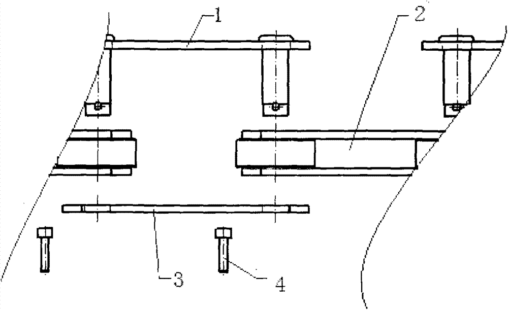
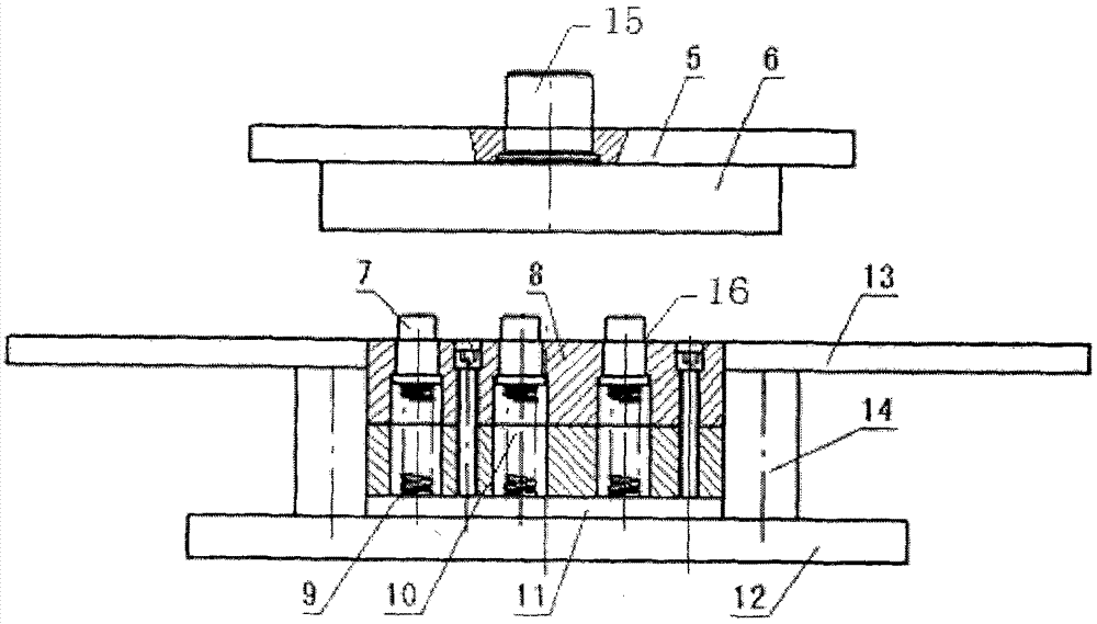
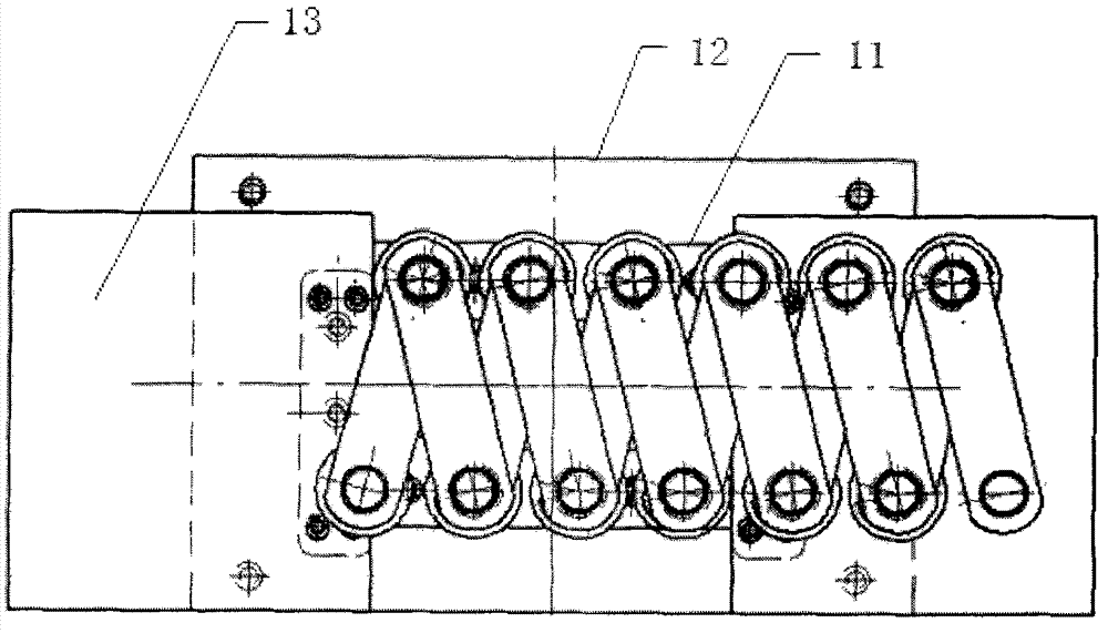
[0024] Such as Figure 1 to Figure 5 As shown, the chain assembly equipment of the present invention includes a hydraulic press (not shown), a hydraulic press panel (not shown), an upper template 5, an upper mold 6 and a bottom plate 12, and the top surface of the upper template 5 is fixed on the hydraulic press The bottom of the hydraulic rod 15, the bottom of which is fixed with the upper mold 6; the top of the working panel of the hydraulic machine is fixed with the base plate 12; the bottom plate 11 is installed above the base plate 12; 12 left and right supporting block pads 14 and left and right supporting blocks 13; core base 8 is installed in the middle of the left and right supporting block pads 14; a plurality of positioning holes 16 are arranged at intervals on the core base 8; inside the positioning holes 16 A core block 9 and a spring 10 are provided; a mandrel 7 is installed on the top of the spring 10 .

[0025] The top surfaces of the left and right supporting...


PUM


Abstract

The invention discloses a device and method for assembling a chain integrally. The device comprises a hydraulic machine, a hydraulic machine work panel, an upper template, an upper die and a bottom board. The top face of the upper template is fixed to the bottom of a hydraulic rod of the hydraulic machine and the bottom of the upper template is fixed to the upper die. The bottom board is fixed to the upper side of the hydraulic machine work panel. A lower bolster is installed above the bottom board. A left supporting block cushion block, a right supporting block cushion block, a left supporting block and a right supporting block are arranged at the two sides of the lower bolster, wherein the left supporting block cushion block, the right supporting block cushion block, the left supporting block and the right supporting block are perpendicular to the bottom board. A core base is installed between the left supporting block cushion block and the right supporting block cushion block. Multiple locating holes are formed in the core base at intervals. Each locating hole is provided with a core base cushion block and a spring. The top end of each spring is provided with a mandrel. The method comprises the steps that firstly, localization is conducted simultaneously through the mandrels; secondly, half outer links to be assembled are arranged in located inner link sleeve holes; thirdly, hinge pins are pressed downwards; finally, the hinge pins bounce up. According to the device and method for assembling the chain integrally, operation is simple, controllability is good, and safety performance is high.

Description

technical field [0001] The invention relates to the field of mechanical processing, in particular to a chain forming assembly equipment and an assembly method. Background technique [0002] The chain generally consists of outer chain plates, inner chain plates, pin shafts, sleeves, rollers, locking parts and other parts; to form a complete chain, it needs to go through semi-outer link assembly, inner chain link assembly, strips, pin shafts, etc. Outcrop and riveting head, installation of locking parts and other processes; the existing half-outer link assembly and inner link assembly are all accurately positioned on the press through tooling molds, and the strip-forming process is generally done by manual work. The chain link and the small hole outer chain plate are connected together, and finally the exposed rivet head of the pin shaft and the locking piece are installed; while the hand-made strip pin and the small hole outer chain plate do not have accurate positioning equi...

Claims


Application Information

Patent Timeline
IPC IPC(8): B21L9/06
Inventor 陈亦兵周健曹永楼邵坚程万春
Owner ANHUI HUANGSHAN HENGJIU CHAIN TRANSMISSION CO LTD
Learn More